Page 2 of 8
Re: Building the KLyball 600D
Posted: Mon May 18, 2015 12:11 pm
by dave
OSI sold C4/8 machines with the 4 MHz 6502C (NMOS part, not the CMOS 65C02). The C1 is a very similar design, so 4MHz should definitely be possible, if your memory is fast enough.
Dave
Re: Building the KLyball 600D
Posted: Mon May 18, 2015 4:02 pm
by BillO
MK14HAK wrote:What CPU are you gentlemen using and what max speed is possible ?
I'm going to start with a 2mHz NMOS 6502A running it a 1mHz for my board memory test, but will switch to a Rokwell 65C02 rated a 4mHz. My RAM is 200ns and my EPROMs are 300ns. I should be able to do 2mHz easily and would even try 4, but I am not sure how well the 6820 will keep up.
Re: Building the KLyball 600D
Posted: Mon May 18, 2015 7:59 pm
by Jeff
Bill, check out the 65C21. It's a modern replacement that should keep up.
/Jeff
Re: Building the KLyball 600D
Posted: Tue May 19, 2015 1:30 pm
by BillO
I said 6820, but meant 6850. It's the ACIA I am worried about. I suppose I could look around for a 68B50, but even they are only rated to 2mHz. Still, it would improve my chances of getting up to 4mHz.
Re: Building the KLyball 600D
Posted: Fri May 22, 2015 5:11 pm
by BillO
Just waiting on the Cherry key switches.

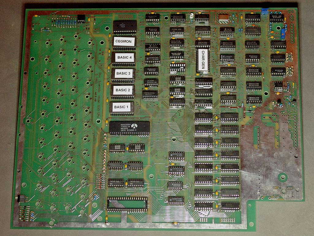
- Otherwise, fully populated
- 600D-2.jpg (243.49 KiB) Viewed 13347 times
Re: Building the KLyball 600D
Posted: Sat May 23, 2015 4:12 am
by Jeff
I see you have the Rockwell CPU installed already.
/Jeff
Re: Building the KLyball 600D
Posted: Sat May 23, 2015 2:42 pm
by BillO
Yes, just in there for the first boot and check out. I have a couple of 1978 vintage NMOS CPUs. One will go in for the memory board tests.
Once the memory board is worked out the Rockwell will go back in. As well, I will be replacing most of the LS logic with ABT, ACT and maybe HCT parts where I can. They produce such clean signals, far less noise, lower propagation delay and lower power consumption. I may even put a WDC65C02 in it.
Re: Building the KLyball 600D
Posted: Tue Jun 23, 2015 5:15 pm
by BillO
Hi Folks,
I'm back to this after a little break. I have the 600D finished. Well, almost finished. It's not working 100%.
First, the characters are coming up backwards. I'm not sure what chargen rom I have, but it's not right. Can anyone post the right one for the 600D or a link to it?
Next, I can get it to the D/C/W/M prompt and into the monitor (backwards....) only if I use a modified WDC65C02 and remove the BASIC2 rom. An NMOS 6502 or Rockwell 65C02 won't work at all. I can dig around until I find the problem, but I'd like to get the characters displaying the right way around.
Re: Building the KLyball 600D
Posted: Tue Jun 23, 2015 6:05 pm
by BillO
Okay, I seem to have solved the booting problem (at least with the WDC65C02 in place).
I found Pin 13 of U73 (the basic2 ROM select line) is connected to pin 8 of U16. Since pin 8 of U16 is the output of an '04 inverter and pin 13 of U73 is the output '138 decoder, they were not seeing eye to eye, so to speak. In fact, the whole U73/U16 relationship is not according to the schematic (only 1 inverter on that chip is currently required). I can see why you did that Grant, to allow the use of EPROMS without having to configure jumpers. However, I believe the U73 Pin 13 to U16 Pin 8 is an error. It may work
'OK' if you are using an 'LS04 and you may not notice it, but since I'm using an 'ACT04 which can source more than the 'LS138 can sink the problem came to light.
Jeff and Grant, can you check that out on your boards as well? For now I just bent pin 8 of U16 out to get things working.
I still need the right CHARGEN though (pretty please!)

Re: Building the KLyball 600D
Posted: Tue Jun 23, 2015 7:22 pm
by Klyball
Hi Bill, I believe in my information sheet I sent with the board showing the 4 missing traces that need to be made the one resistor to put in the other hole , I believe I made a note to leave that pin out of the socket, when I made the mod my trace was still connected on that pin, it does not boot otherwise ,that one got me for a while also. I did that as the odds of someone building the replica and have original roms is unlikely .
I originally had 8t26 in the video section that's bad ,need to be 8t28.
Double check the 2 jumpers that need to be made in the video section and the resistor connection .