Page 1 of 4
Building the KLyball 610
Posted: Fri May 08, 2015 6:25 am
by Jeff
I too picked up a 610 replica and a pair of data separators from Grant and am going to use them to add a floppy drive interface (and optionally, RAM) to my recently acquired C1P. The second separator will be used to add a different floppy drive to my C1PMF, hopefully restoring it to full functionality. (but that is another thread).
I am not
currently planning to populate the RAM portion of the board, instead opting to employ some sort of RAM/ROM board.
Here is my progress so far:
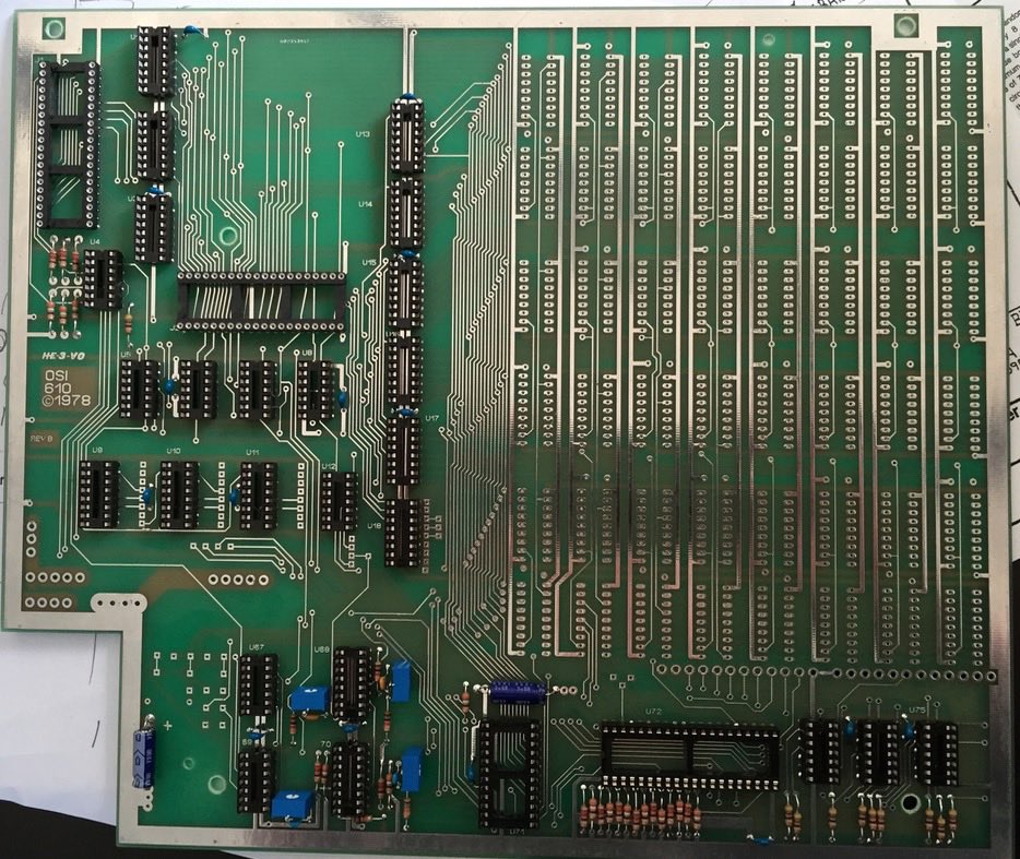
- 610sofar.jpg (208.09 KiB) Viewed 16352 times
Re: Building the KLyball 610
Posted: Fri May 08, 2015 6:42 am
by Jeff
Here is my parts list, complete with links where to buy components.
Here are two handy chip placement guides.
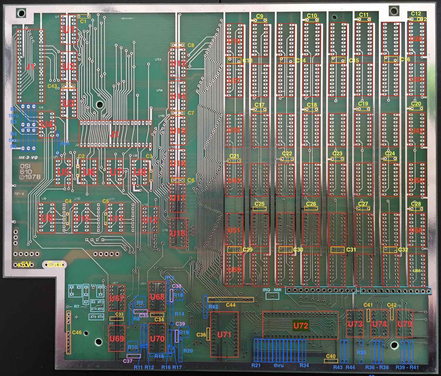
- 610 LayoutSml.jpg (239.49 KiB) Viewed 16337 times
This one is courtesy OSI.
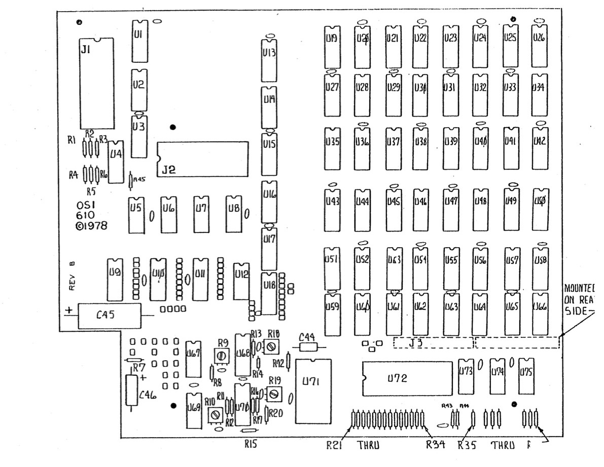
- 610 Chip Layout.jpg (232.6 KiB) Viewed 16350 times
UPDATE: revised color PCB layout file; added RAM chips and jumpers
/Jeff
Re: Building the KLyball 610
Posted: Fri May 08, 2015 1:34 pm
by BillO
Thanks Jeff!
Re: Building the KLyball 610
Posted: Fri May 08, 2015 5:53 pm
by Jeff
Here is info on setting the jumpers for Single or Dual sided floppies:
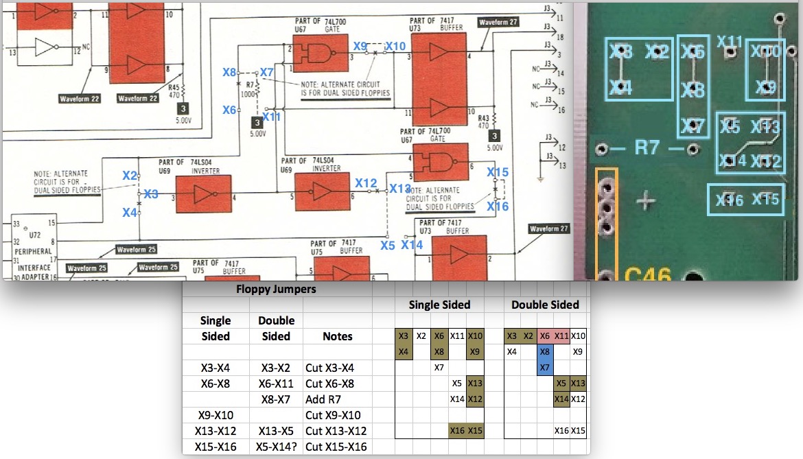
- 610 FloppyJumpers.jpg (205.02 KiB) Viewed 16337 times
Im not sure about X5-X14. Can anyone in the know verify this jumper for double-sided?
Also, R7 is 1K ohms.
/Jeff
Re: Building the KLyball 610
Posted: Fri May 08, 2015 11:03 pm
by Jeff
Today I finished off the board (except for the floppy disk separator board) and tested it with 4K of RAM. I plugged it in and it fired up beautifully!
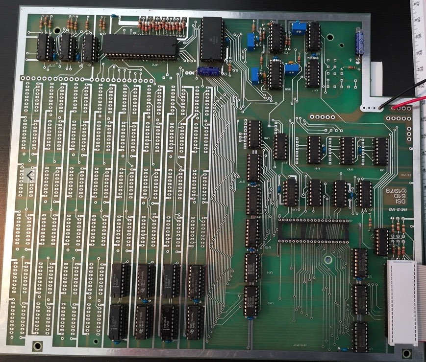
- CompleteWith4K.jpg (241.28 KiB) Viewed 16328 times
Here is what I was greeted with when I turned it on:
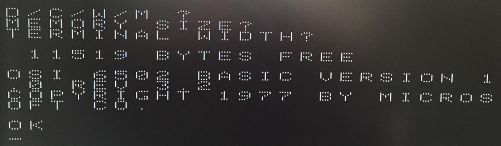
- Boot12K.jpg (70.53 KiB) Viewed 16328 times
Now I have to build the separator and acquire a floppy. I have purchased this drive from eBay, but it hasn't arrived yet. It should arrive next week.
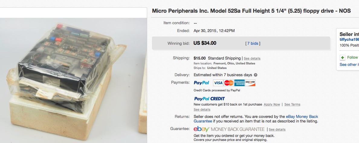
- Drive.jpg (147.76 KiB) Viewed 16328 times
Hopefully I will be able to get it going!
/Jeff
Re: Building the KLyball 610
Posted: Sat May 09, 2015 2:15 pm
by BillO
Great progress Jeff! This is so cool!
The parts for my 600 board are slowly coming in. I should just have spent the money and gotten everything form Digikey, but I've tried to keep the cost down (fixed income and all

) and ordered a few things from the far east (like the Cherry key switches).
Re: Building the KLyball 610
Posted: Sat May 09, 2015 5:10 pm
by Jeff
@Bill, well look at it this way, you can savour the project longer ;-D
/Jeff
Re: Building the KLyball 610
Posted: Tue May 12, 2015 10:24 pm
by Klyball
Looking good.
I think R20 could be a miss print, as I needed to change it to 1k to get the timing signal correct.
Re: Building the KLyball 610
Posted: Wed May 13, 2015 12:28 am
by Jeff
Can anyone with an actual OSI 610 confirm the value of R20?
/Jeff
Re: Building the KLyball 610
Posted: Fri May 15, 2015 2:16 am
by Jeff
Today I made the electrical adjustments on the 610 so support reading and writing to the floppy drive. I figured I would post the procedure so that the information is central for future builders.
R18 TX Clock
Remove floppy-disk cable (J3).
Input of scope to pin 13 of U68.
Adjust R18 for a positive pulse width of 400nSec +- 50nSec.
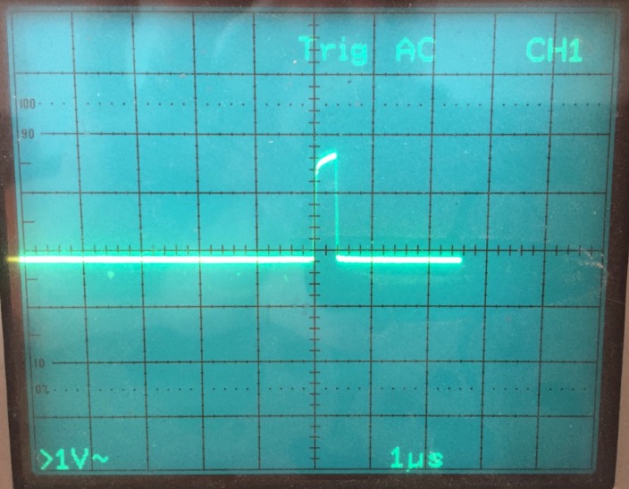
- R18 Adjustment.jpg (101.5 KiB) Viewed 16245 times
R9 TX Data
Remove floppy-disk cable (J3).
Input of scope to pin 12 of U68.
Adjust R9 for a negative pulse width of 400nSec +- 50nSec.
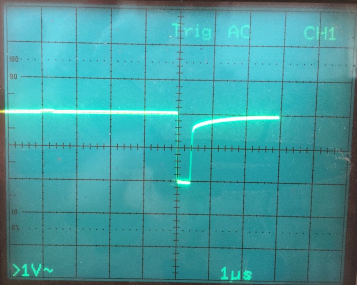
- R9 Adjustment.jpg (104.79 KiB) Viewed 16245 times
continued in next post...