Page 1 of 8
Building the KLyball D-13
Posted: Sun May 17, 2015 4:14 pm
by Klyball
Here are the parts placement and parts list for the data separator,
http://klyball.com/OSI/data/D-13.rar
1 problem we have run into is the drills holes for the 34 and 50 pin connectors are to small to fit some of the connectors, the one’s i had on hand worked for me but others have had problems , they can not have plated pin on the solder side of the connector, i have ordered this part digikey #A33168-ND but won’t be able to confirm it will work until i receive it this coming week. The .156 connectors can be placed on either side and male or female depending on you application and +5 needs to get to pin 14 on the 610 board the 500 series has this already.
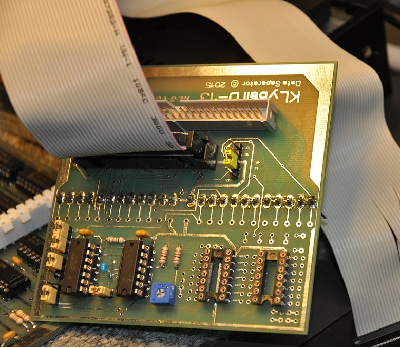
- 1.JPG (245.29 KiB) Viewed 53886 times
Re: Building the KLyball D-13
Posted: Sun May 17, 2015 5:06 pm
by BillO
Hi Grant, that link to digikey does not seem to be working.
Re: Building the KLyball D-13
Posted: Tue May 19, 2015 8:18 pm
by Jeff
In order to calibrate TR1 I had to short pin 9 on the OSI connector with pin 1 of IC1 (I hooked to J3).
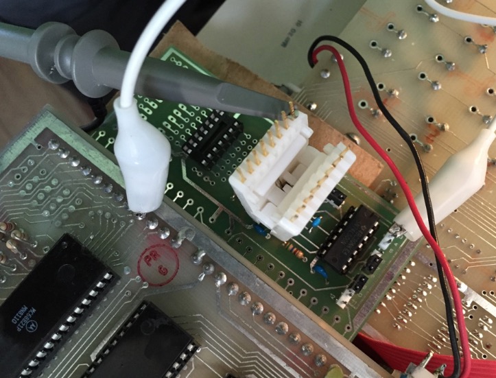
- Klyball D13 installed in C4PMF.jpg (124.36 KiB) Viewed 53859 times
Then I adjusted TR1 for a negative pulse width of 6 microseconds.
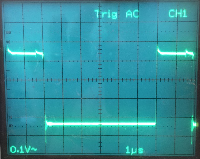
- TR1 Adjustment.jpg (84.45 KiB) Viewed 53859 times
/Jeff
Re: Building the KLyball D-13
Posted: Tue May 19, 2015 11:59 pm
by Klyball
I can confirm these parts fit the holes.
digikey part #
34 pin A33168-ND
50 pin MHC50K-ND
Re: Building the KLyball D-13
Posted: Fri May 22, 2015 5:07 pm
by BillO
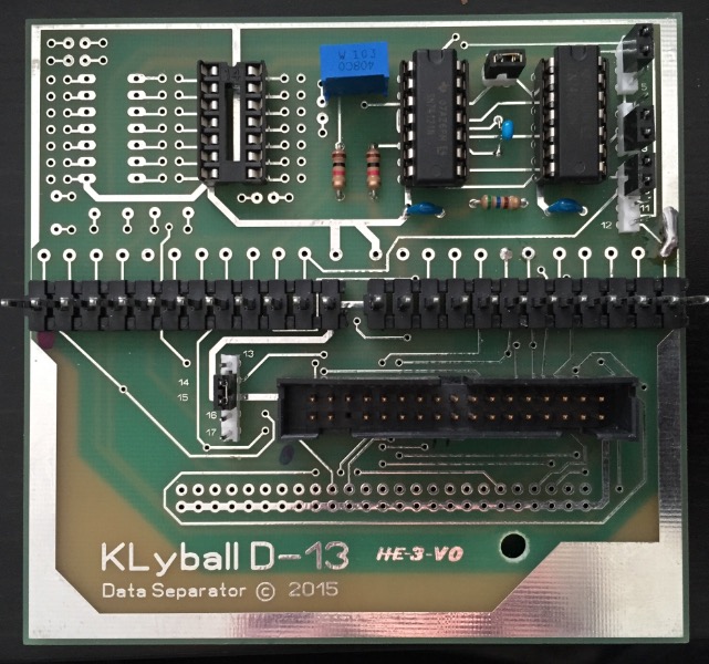
Ready to go.

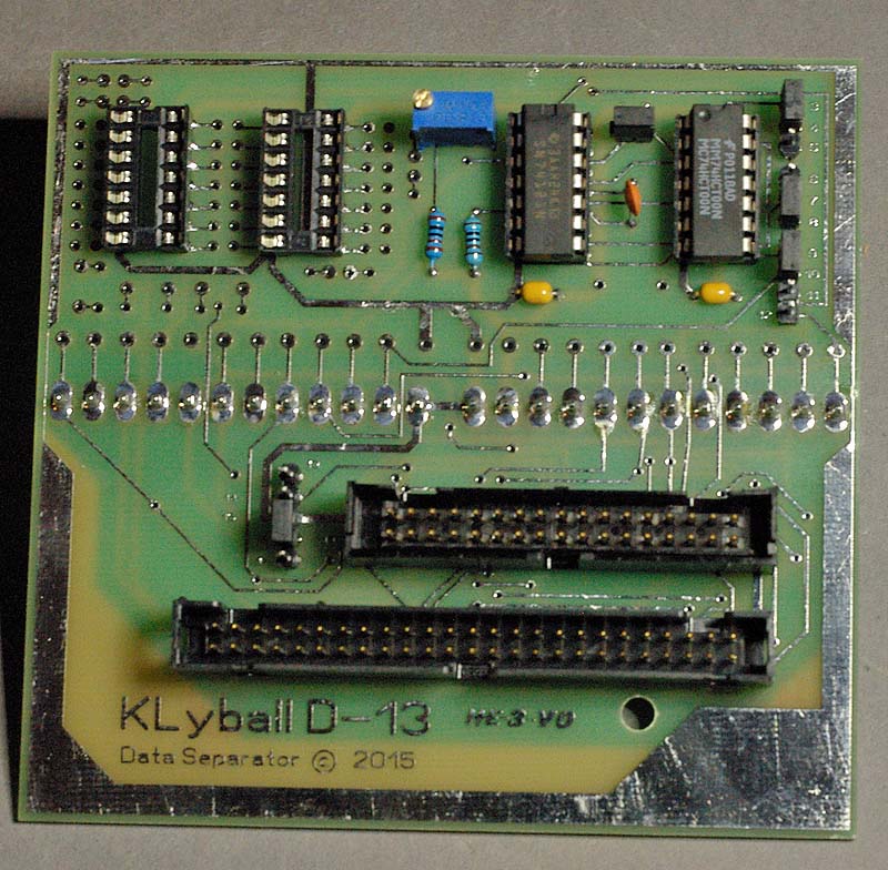
- KLyball D-13 Data Separator
- D-13.jpg (157.57 KiB) Viewed 53836 times
Re: Building the KLyball D-13
Posted: Mon Jun 01, 2015 4:12 am
by Klyball
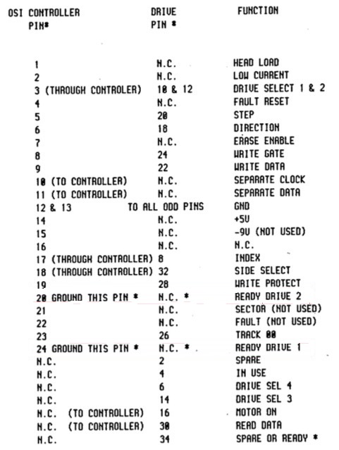
Here is a modification to use 2 sided drives,
my original design is based on connecting a 610 to single sided drives with the side select for drive 2
this mod with make the board more versatile
original pinout
OSI-610 J3 // Pin Function // FDD Connector Pin
1 // Head Load // 2
3 // Select Drive 1 // 10
5 // Step // 20
6 // Step Direction // 18
8 // Write Enable // 24
9 // Write Data // 22
10 // Receive Clock // From Data Separator
11 // Receive Data // From Data Separator
12 // Ground All ODD Pins
13 // Ground All ODD Pins
17 // Index // 8
18 // Select Drive 2 // 12
19 // Write Protect // 28
20 // To Ground
23 // Track 00 // 26
24 // To Ground
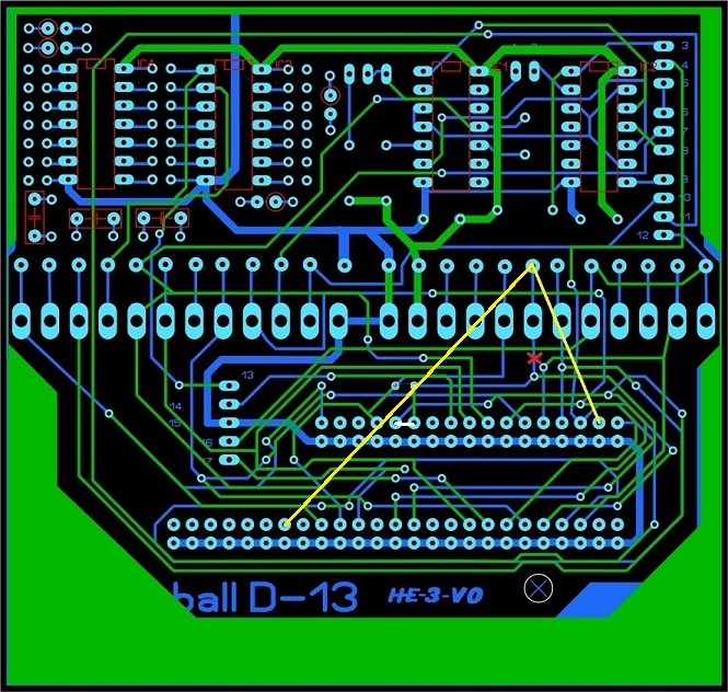
red=cut
yellow=jump
white=2 drives as per pin out below

- data%20separator2.jpg (213.16 KiB) Viewed 53760 times
- pinout.jpg (82.05 KiB) Viewed 53796 times
Re: Building the KLyball D-13
Posted: Mon Jun 01, 2015 8:08 pm
by BillO
Hi Grant
Maybe I'm mistaken, but won't this mod kind of break things for 8" drives?
Would it not be better to make that cut after the via that takes the drive select to the 50 pin connector (from PIN 18 of the controller)?
Re: Building the KLyball D-13
Posted: Mon Jun 01, 2015 10:38 pm
by Klyball
I guess it really depends what type of drives are being used, for 2 sided 8 inch you would need to jump from 18 to pin 14 of 50 pin connector , the cut would be fine where it is. i think being set up for 2 sided drives would be the most practical, the way it is the side select is used like a drive select. So going to 2 sided drive you need to make the modification on the controller board and the separator board.
5.25" 8" Function
4 18 Head load (-in-)
6 32 Drive select 4 (-in-)
8 20 Index sector pulse (-out-)
10 26 Drive select 1 (-in-)
12 28 Drive select 2 (-in-)
14 30 Drive select 3 (-in-)
16 Motor on (-in-)
18 34 Step direction (in or out) (-in-)
20 36 Step pulse (-in-)
22 38 Write data (-in-)
24 40 Write gate (enable write) (-in-)
26 42 Track 0 pulse (-out-)
28 44 Write protect (-out-)
30 46 Read data (-out-)
32 14 Side select (-in-)
34 22 Ready (-out-) (If not available index pulse may be
- data%20separator2.jpg (213.16 KiB) Viewed 53760 times
Re: Building the KLyball D-13
Posted: Tue Jun 02, 2015 3:48 am
by Jeff
Also complete. (I don't ever plan to connect 8" drives.) I do plan to add the motor control IC shortly.
- Klyball D13 for C1P.jpg (136.26 KiB) Viewed 53773 times
/Jeff
Re: Building the KLyball D-13
Posted: Tue Jun 02, 2015 4:56 pm
by BillO
Klyball wrote:I guess it really depends what type of drives are being used, for 2 sided 8 inch you would need to jump from 18 to pin 14 of 50 pin connector , the cut would be fine where it is. i think being set up for 2 sided drives would be the most practical, the way it is the side select is used like a drive select. So going to 2 sided drive you need to make the modification on the controller board and the separator board.
A few more questions Grant.
1) So you have to make this modification and a modification to the controller (610)? Do you have a link to that mod?
2) From the drawing, it looks like the little white jumper connects Index (8) to Drive Select 2 (12), is this correct? Is this done as a part of the double sided mod, or to go back to 2 separate single sided drives?