Page 4 of 4
Re: Building a C4P Replica
Posted: Fri Aug 23, 2019 12:29 am
by Jeff
I have created a diagram to help me wire all the boards together. Posting it here in case others might find it useful.
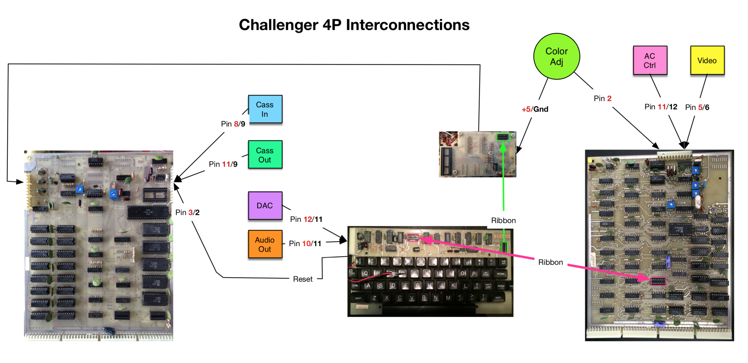
- Interconnect.jpg (1.27 MiB) Viewed 9051 times
/Jeff
Re: Building a C4P Replica
Posted: Thu Sep 05, 2019 2:12 am
by Jeff
Here is a couple of photos of the project so far.
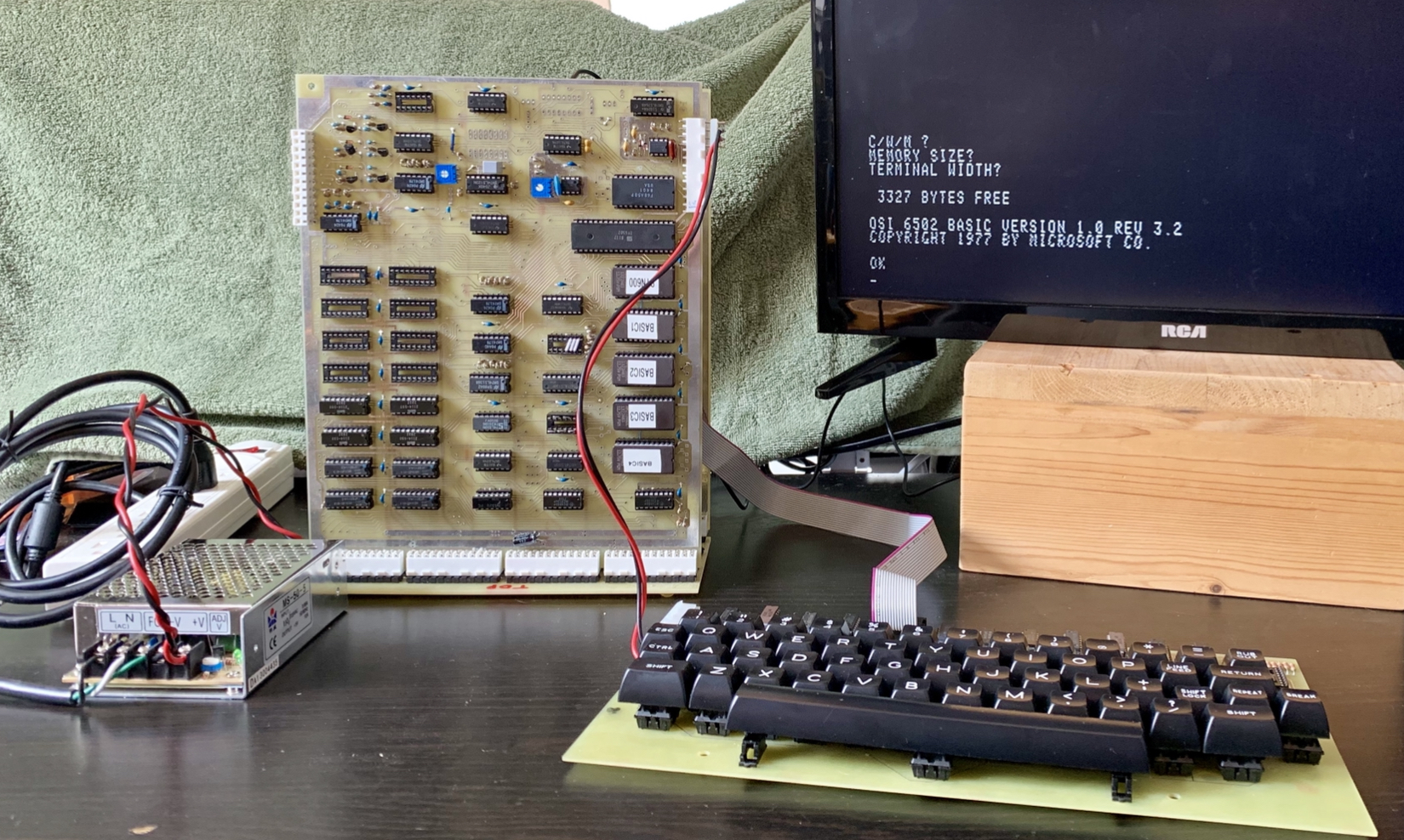
- 190C97B3-D109-4B6D-8411-D1618ACA36CE.jpeg (1.55 MiB) Viewed 8959 times
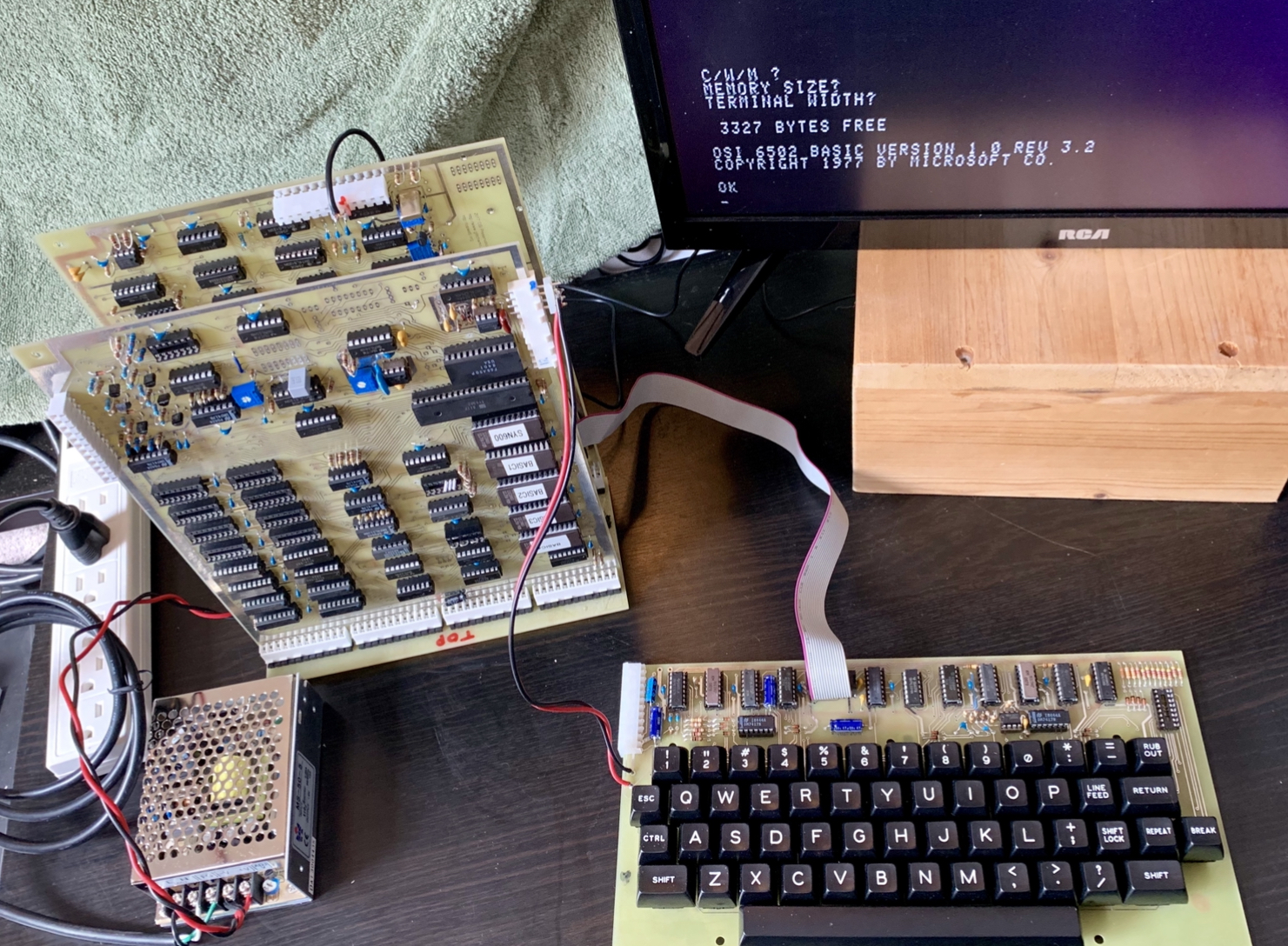
- 4F04651F-4D11-49CA-81BB-AF4839D9C924.jpeg (1.63 MiB) Viewed 8959 times
/Jeff
Re: Building a C4P Replica
Posted: Tue Jul 21, 2020 1:56 am
by musovern
Great work Jeff.
I've just finished putting these board together as well.
I've got the 502,540B,542C keyboard as well. And I'm ready to test startup is there any tips you could share before I switch on.
On the 540B board are you coming out pins 5 & 6 for your monitor output.?
Also on your 502 board is that the minimum RAM (4K) to get started ?
Regards
Vernon
Re: Building a C4P Replica
Posted: Wed Jul 22, 2020 6:12 pm
by Jeff
Hi Vernon,
I diagnosed each board separately by swapping them into my working C4P one at a time.
The minimum RAM is 1K (2 chips), so the 6502 has a zero page of RAM (256 bytes).
On the 540B, pin5 is Video signal, pin 6 is ground.
Also, I temporarily changed which pages in the SYN600 were the boot pages, so I could test just the ROMS, one at a time. The default CWM page uses routines in the basic ROMS to do its stuff, so if they are bad, you get nothing. HWM, doesn't rely on anything in the basic ROMS, so you can use the M monitor to examine and set memory locations. It turned out that my programmed EPROMS were not up to snuff and were failing.
So glad to hear that someone else is building one!
/Jeff
Re: Building a C4P Replica
Posted: Thu Jul 23, 2020 11:19 pm
by musovern
Hi Jeff,
Thank you for the info on RAM. I must admit I have been using your photos and diagrams to put my system together and it's been so helpful.
I would be keen to know how you temporarily changed which pages in the SYN600 were the boot pages, so I could test just the ROMS, one at a time. I have made sure that I checked my ROM images that I burnt off a few times and i'm sure they are ok. I used my ME2700 Programmer in the end and checked that the checksums were the same.
Unfortunately I don't have the luxury of having the C4P to test each board separately. This is my first OSI type system as they are a little hard to come by in New Zealand. At the moment my screen is showing a whole lot of garbage with random characters and the system doesn't seem to reset using the break key. As far as I know I have done all the same mods as you have done on the 502/540B/542 Rev C. and a 580 Backplane.
Please see my attached photos. If you can offer any suggestions that would be great.
Thanks, Vernon
Re: Building a C4P Replica
Posted: Fri Jul 24, 2020 6:52 pm
by dave
Hi Vernon!
Your build looks beautiful. You are getting video output, so that means that your video board is at least 99% working.
There are plenty of ways to tackle this. Maybe the easiest would be to first make sure your CPU is working. You can use a serial monitor and the on-board UART to test out the basic CPU board functionality. The serial monitor is not included in the SYN600 ROM, though. You will have to use the
SYNMON1 ROM, and select the 65V serial monitor using your ROM-select jumpers.
Once you have the serial monitor up and running, you can attempt to store data in the video memory starting at D000. If you run a little program to repeatedly store a byte somewhere toward the middle of the screen, then you should see the character appear, and can check the 540 address, data, and enable lines to see if all the parts are working right.
Cheers,
Dave
Re: Building a C4P Replica
Posted: Sat Jul 25, 2020 4:30 am
by musovern
Thanks Dave,
I've made a new EPROM with SYNMON1 what address am I setting for the 65V serial monitor at the ROM-select jumpers.? Is it FC00.?
And should I take out the basic ROMs or leave them in.?
Also for the serial out should I use the J1 connector and wire up for TTL serial output to USB or the J3 connector and use RS232.? what baud rate would you recommend for this connection.
Is there a manual in the downloads section which I should be reading up on any suggestion would be of great help.
Thanks
Vernon
Re: Building a C4P Replica
Posted: Sat Jul 25, 2020 4:02 pm
by Jeff
Hi Vernon,
Beautiful build!
1) Remember Shift Lock needs to be ON when pressing Break.
2) Here is my notes for ROM page jumpers for the SYN600 ROM. Use the second map for testing ROMS. H and D wont work, but you will get M, without relying on the BASIC ROMS needing to be working. (They do not even need to be present).
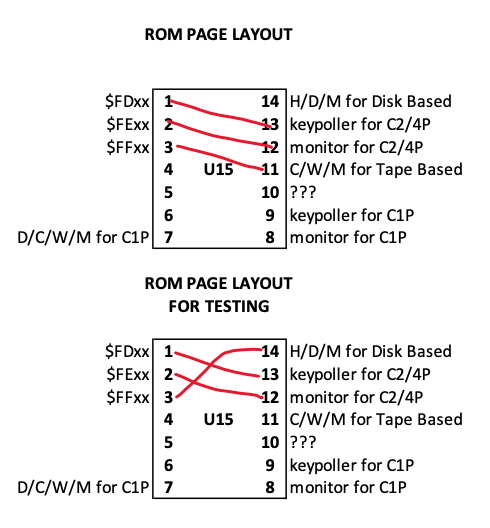
- Rom Page Jumpers.png (70.42 KiB) Viewed 7317 times
/Jeff
Re: Building a C4P Replica
Posted: Sat Jul 25, 2020 6:03 pm
by dave
Nice drawings, Jeff!
In those drawings, pin 7 is page 0 of the ROM, and pin 14 is page 7.
Here's the mapping for SYNOMN1 (cut/pasted from Peek(65) Vol 5 N 1:
Jumper Page
PIN Number Name Address Description
------ ---- ---- ------- -----------
14 0 65V2P $FEOO 65V Monitor for 540 Video and ASCII keyboard
13 1 65VB73 $FFOO ROM BASIC Support for 540 Video & ASCII keyboard
12 2 65K $FDOO Polled keyboard Driver
11 3 65VK $FEOO 65V Monitor for 540 Video and Polled Keyboard
10 4 65VB76 $FFOO ROM BASIC Support for 540 Video & Polled keyboard
9 5 65H $FFOO? CD-74 Hard Disk Boot Code
8 6 65A $FEOO Serial Monitor
7 7 65F3 $FFOO "H/D/M?" Floppy Disk Boot
So, with SYNMON1 installed, for a serial monitor, you want to map :
- page 7 to FF00 (pin 14 to pin 3)
- page 6 to FE00 (pin 13 to pin 2)
- page 2 to FD00 (pin 12 to pin 1)
For Video monitor and no BASIC, you would map:
- Page 7 to FF00 (pin 14 to pin 3)
- Page 3 to FE00 (pin 11 to pin 2)
- Page 2 to FD00 (pin 12 to pin 1)
For BASIC-in-ROM with video monitor:
- Page 4 to FF00 (pin 10 to pin 3)
- Page 3 to FE00 (pin 11 to pin 2)
- Page 2 to FD00 (pin 12 to pin 1)
Cheers,
Dave