Time to build a 540B-1 replica.
-
pbirkel
- Posts: 34
- Joined: Mon Feb 27, 2017 8:06 am
Re: Time to build a 540B-1 replica.
Now collecting parts for mine :->. Can anyone identify a supplier for X1 = 12.08 MHz?
-
CommodoreZ

- Posts: 50
- Joined: Wed Oct 17, 2018 11:16 am
- Contact:
Re: Time to build a 540B-1 replica.
Finally getting back around to this project while I await some missing stuff for 400 board.
My replica 540B has been gathering dust for too long now. For the past few days when I have had time, I've been examining the signals with my oscilloscope to figure out what's wrong with it.
I spotted a solder bridge attaching pin 11 of U4E (the signal known as /COL_CLR) to some other signal that was chronically low. The result was that the output of the NAND gate on pin 11 would never go above 1V, and thus never trigger the master reset on three of the 74LS163s. This cascaded into the END_BLANK signal never triggering, so the signal would be stuck blanking the video forever. The solder bridge is marked in red.
After that was fixed, I started to see more sane signals in a few places, which is promising! I've also noted that adjusting the color phase trimcap is very difficult, it requires alot of force, and just the right screwdriver, and I usually end up capacitively coupling the screwdriver to the trimcap which throws the timing off. I feel like I'm right on the verge of acceptable color, but I can see something on screen finally. It's yellow! However, I'd like to replace that trimcap if possible with something higher quality, and I'm open to suggestions for reputable parts.
The Sam's C4P manual that I should be seeing horizontal sync pulse of 4.7microseconds from U4B pin 12, per NTSC spec. I'm seeing closer to 8microseconds. I'm also seeing a vertical sync pulse on U4A pin 12 of close to 360microseconds rather than the suggested 300. I know it says "approximately" in the manual but my inner broadcast engineer is mad at me. Would you say these values are common for 540B build?
In looking at the video signal output by my board on my oscilloscope, I'd say it's getting closer to sane. My monitor accepts it, but I can't see the color burst or anything approaching a front or back porch on the scope. Sadly I'm not yet seeing anything on screen but a solid color.
I've also gotten frustrated trying to read the schematics within the Sam's C4P document floating around, as they're split between pages within the PDF. Solution? A little photoshop and the 540B schematics are now glued together into two contiguous pages, making it easier for me to follow signals. I imagine the original physical copy was one bit foldout. Maybe they'll help someone else.
My replica 540B has been gathering dust for too long now. For the past few days when I have had time, I've been examining the signals with my oscilloscope to figure out what's wrong with it.
I spotted a solder bridge attaching pin 11 of U4E (the signal known as /COL_CLR) to some other signal that was chronically low. The result was that the output of the NAND gate on pin 11 would never go above 1V, and thus never trigger the master reset on three of the 74LS163s. This cascaded into the END_BLANK signal never triggering, so the signal would be stuck blanking the video forever. The solder bridge is marked in red.
- bridge.png (1.02 MiB) Viewed 9618 times
The Sam's C4P manual that I should be seeing horizontal sync pulse of 4.7microseconds from U4B pin 12, per NTSC spec. I'm seeing closer to 8microseconds. I'm also seeing a vertical sync pulse on U4A pin 12 of close to 360microseconds rather than the suggested 300. I know it says "approximately" in the manual but my inner broadcast engineer is mad at me. Would you say these values are common for 540B build?
- 20230510_112338.jpg (2.91 MiB) Viewed 9618 times
I've also gotten frustrated trying to read the schematics within the Sam's C4P document floating around, as they're split between pages within the PDF. Solution? A little photoshop and the 540B schematics are now glued together into two contiguous pages, making it easier for me to follow signals. I imagine the original physical copy was one bit foldout. Maybe they'll help someone else.
- Attachments
-
- Sam's 540 Schematic 2.jpg (3.68 MiB) Viewed 9618 times
-
- Sam's 540 Schematic 1.jpg (4.28 MiB) Viewed 9618 times
Superboard Replica (400, 420C, 440) | C4P (502, 540) | Mini OSI-300 | https://www.commodorez.com 

-
pbirkel
- Posts: 34
- Joined: Mon Feb 27, 2017 8:06 am
Re: Time to build a 540B-1 replica.
"Maybe they'll help someone else."
Undoubtedly; thank you :-}.
Undoubtedly; thank you :-}.
-
dave
- Site Admin
- Posts: 717
- Joined: Tue Sep 09, 2008 5:24 am
Re: Time to build a 540B-1 replica.
Nice work on the build!
I don't know which C4p Sam's manual is floating around, but the 300 dpi and 600 dpi versions on osiweb.org, scanned by Jeff Ferguson, keep each schematic fold-out complete, one per page:
300 DPI Sam's C4P manual
600 DPI Sam's C4P manual
Keep us posted on your progress!
Dave
I don't know which C4p Sam's manual is floating around, but the 300 dpi and 600 dpi versions on osiweb.org, scanned by Jeff Ferguson, keep each schematic fold-out complete, one per page:
300 DPI Sam's C4P manual
600 DPI Sam's C4P manual
Keep us posted on your progress!
Dave
-
CommodoreZ
- Posts: 50
- Joined: Wed Oct 17, 2018 11:16 am
- Contact:
Re: Time to build a 540B-1 replica.
Finally back on this project after... forever. Needed a break from the 400 + 440 stuff.
I was running through signals, trying to debug the 540B replica, and noticed that the video signal lacked any pixel data. Just sync data was present. I was seeing something coming out of the video shift register, getting past XOR gate U2B, but not getting past a NAND gate U4E. The Dot Inhibit signal wasn't leaving U3G, a bank of flip flops, and I couldn't see why. I checked for shorts to ground on pins 10, 7, and 11, no dice. Then I noticed that noting was leaving U3G at all, no flip flop was flipping or flopping, despite having data input and a clock. Master reset was stuck low, but it only goes between two IC's and a pull-up resistor. And then I spotted it:
Solder bridge. It was coming from another signal, rather than ground itself, which explained the lack of continuity. That's the second solder bridge I've had on this thing which has tripped up the logic.
I wasn't getting any video initially, until I started tweaking the trimpots and suddenly... GARBAGE ON SCREEN! Then one reset later, the C/W/M? prompt!
Sure enough, there was video! Success!
I've run a test or two, but so far I haven't been able to get video levels bright enough. I'm going to have to do some scope comparisons to known-good signals and dial things in from there, possibly adjust some resistor values.
So now I get to try programming some color video to see if I got that's working right, and I have no idea how best to test it yet.
I was running through signals, trying to debug the 540B replica, and noticed that the video signal lacked any pixel data. Just sync data was present. I was seeing something coming out of the video shift register, getting past XOR gate U2B, but not getting past a NAND gate U4E. The Dot Inhibit signal wasn't leaving U3G, a bank of flip flops, and I couldn't see why. I checked for shorts to ground on pins 10, 7, and 11, no dice. Then I noticed that noting was leaving U3G at all, no flip flop was flipping or flopping, despite having data input and a clock. Master reset was stuck low, but it only goes between two IC's and a pull-up resistor. And then I spotted it:
- bridge2.png (1.96 MiB) Viewed 371 times
I wasn't getting any video initially, until I started tweaking the trimpots and suddenly... GARBAGE ON SCREEN! Then one reset later, the C/W/M? prompt!
- 20240321_094936.jpg (1.87 MiB) Viewed 371 times
- 20240321_092743.jpg (3.57 MiB) Viewed 371 times
So now I get to try programming some color video to see if I got that's working right, and I have no idea how best to test it yet.
Superboard Replica (400, 420C, 440) | C4P (502, 540) | Mini OSI-300 | https://www.commodorez.com
-
nama
- Posts: 369
- Joined: Wed Mar 30, 2011 9:44 am
- Location: New Zealand
- Contact:
Re: Time to build a 540B-1 replica.
Good job!
I just built a 540b card but sync is pretty bad...just curious what crystal you are using?
I'm using 12mhz, but thinking to change it out for a 12.096mhz as the are readily available.
I just built a 540b card but sync is pretty bad...just curious what crystal you are using?
I'm using 12mhz, but thinking to change it out for a 12.096mhz as the are readily available.
2P (1mhz 32k) - 502 + 8k + CEGMON + garbage collector fix BASIC, D&N MEM-CM9 + 24k, 540 (mono) [SOLD]
4PMF (2mhz 24k) - 505, 540, 527, D13 + 5.25" + Gotek
Superboard RevD - CEGMON + 610 board 24k + D13
Spares - 3 x 527, 1 x 505, Backplane
-
Mark
- Posts: 297
- Joined: Tue Sep 16, 2008 6:04 am
- Location: Madison, WI
- Contact:
Re: Time to build a 540B-1 replica.
Good catch!
I have some photos from my OSI built C4P on a CRT and the program used to generate a test pattern in case you are interested.
One thing that may not be included on the schematics -- on the RCA connector on the back of the OSI there is a .01uf cap soldered across the terminals. The fine color adjust pot on back of the C4P generally needs to be adjusted to reduce the chroma noise or phase distortion.
Nothing special, just a test program I whipped up to test video one time...
"Never Twice the Same Color"
Same image on LCD TV
I have some photos from my OSI built C4P on a CRT and the program used to generate a test pattern in case you are interested.
One thing that may not be included on the schematics -- on the RCA connector on the back of the OSI there is a .01uf cap soldered across the terminals. The fine color adjust pot on back of the C4P generally needs to be adjusted to reduce the chroma noise or phase distortion.
Nothing special, just a test program I whipped up to test video one time...
Code: Select all
 1 POKE 56900,5
 5 J=13*4096
 10 I=14*4096
 20 FOR R=0TO31
 30 FOR C=0TO63
 40 POKE I+R*64+C,R
 50 POKE J+R*64+C,R*6+C
 60 NEXT C,R
70 GOTO 70- Sony CRT
- CRT_1.JPG (653.71 KiB) Viewed 365 times
- CRT
- CRT_2.JPG (1023.87 KiB) Viewed 365 times
Same image on LCD TV
- LCD TV
- LCD.JPG (1002.13 KiB) Viewed 365 times
- Attachments
-
- fillcolor.txt
- BASIC program used to generate test pattern
- (155 Bytes) Downloaded 16 times
-
CommodoreZ
- Posts: 50
- Joined: Wed Oct 17, 2018 11:16 am
- Contact:
Re: Time to build a 540B-1 replica.
I looked back through my purchase history, and I think mine is also a 12MHz crystal.
Superboard Replica (400, 420C, 440) | C4P (502, 540) | Mini OSI-300 | https://www.commodorez.com
-
CommodoreZ
- Posts: 50
- Joined: Wed Oct 17, 2018 11:16 am
- Contact:
Re: Time to build a 540B-1 replica.
Thank you, I will give this a try soon.Mark wrote: ↑Thu Mar 21, 2024 6:51 pm I have some photos from my OSI built C4P on a CRT and the program used to generate a test pattern in case you are interested.
One thing that may not be included on the schematics -- on the RCA connector on the back of the OSI there is a .01uf cap soldered across the terminals. The fine color adjust pot on back of the C4P generally needs to be adjusted to reduce the chroma noise or phase distortion.
Nothing special, just a test program I whipped up to test video one time...
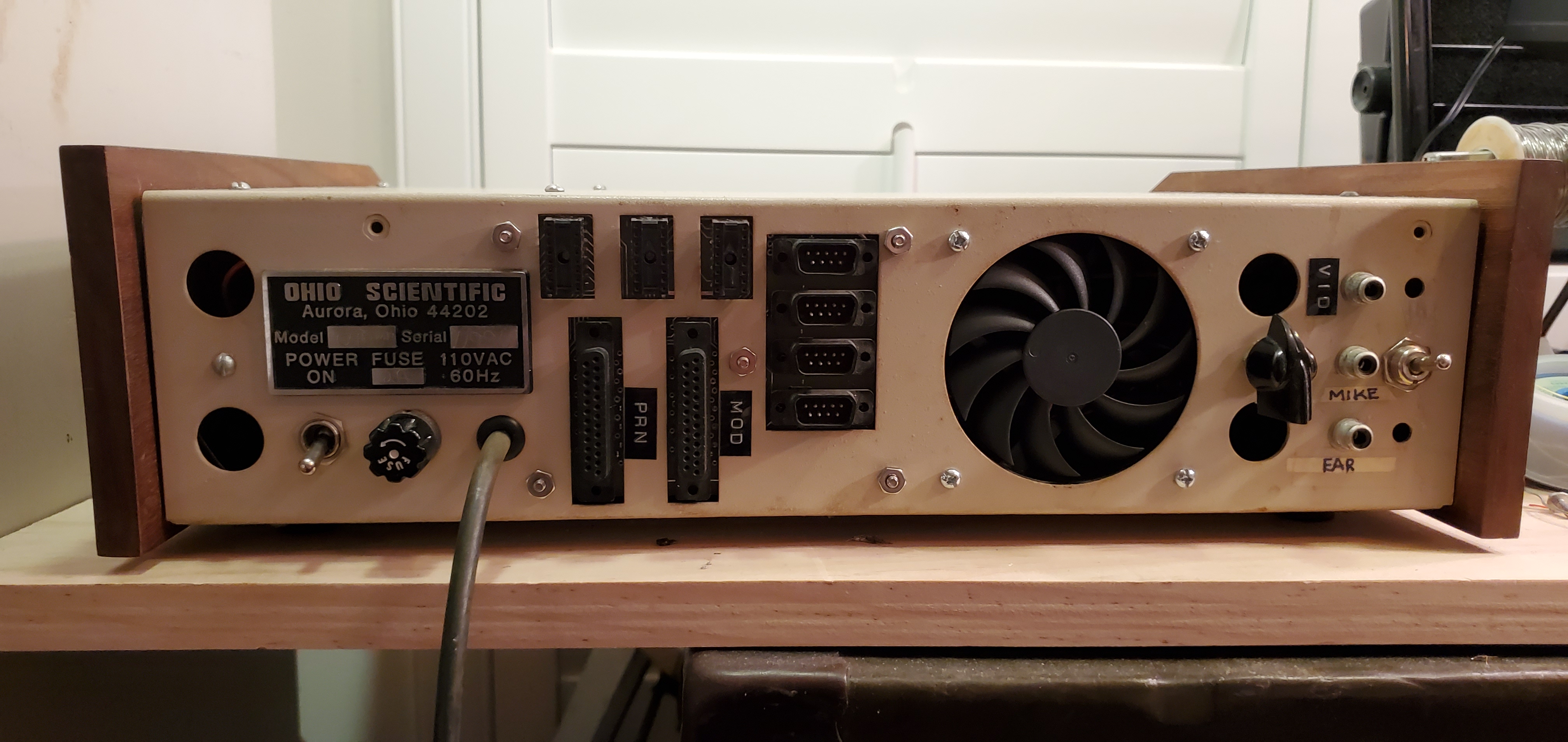
I have not spotted a 0.01uF bridged across the RCA output connector on mine. I will consider adding one. The original RCA connector back there is flaky and needs to be replaced (as does the internal video cable), so I'm considering putting in a BNC connector to match the rest of my equipment. Here's an old photo from after I installed an A15 board and a fan, but before I found a suitably sized fan grill. https://www.commodorez.com/OSIC4P/backs ... proved.jpg
My C4P was built as a monochrome unit, this replica moving it to color is an upgrade, so there is no fine color adjust pot on the back. In fact, there were no video adjustments back there.
Still, the video is very dark so that's the biggest thing that will need fixing. Adjusting the R9 potentiometer (video level) doesn't seem to have any visible effect on screen nor on my scope, nor does R10 (color). Only R23 (sync) and (R5) bias seem to do anything of note. I also added the optional R22 (blanking) but I can see now why that's been omitted from other people's builds.
Superboard Replica (400, 420C, 440) | C4P (502, 540) | Mini OSI-300 | https://www.commodorez.com
-
glitch

- Posts: 176
- Joined: Mon Nov 28, 2011 12:43 am
Re: Time to build a 540B-1 replica.
Great to see another 540B running, especially with color!
Check out The Glitch Works
OSI Challenger 3, 510 CPU, 8" floppies, 23 MB hard disk system starting to work!
Parts bin Challenger 3 board set, never had a chassis in its time
OSI Challenger 3, 510 CPU, 8" floppies, 23 MB hard disk system starting to work!
Parts bin Challenger 3 board set, never had a chassis in its time