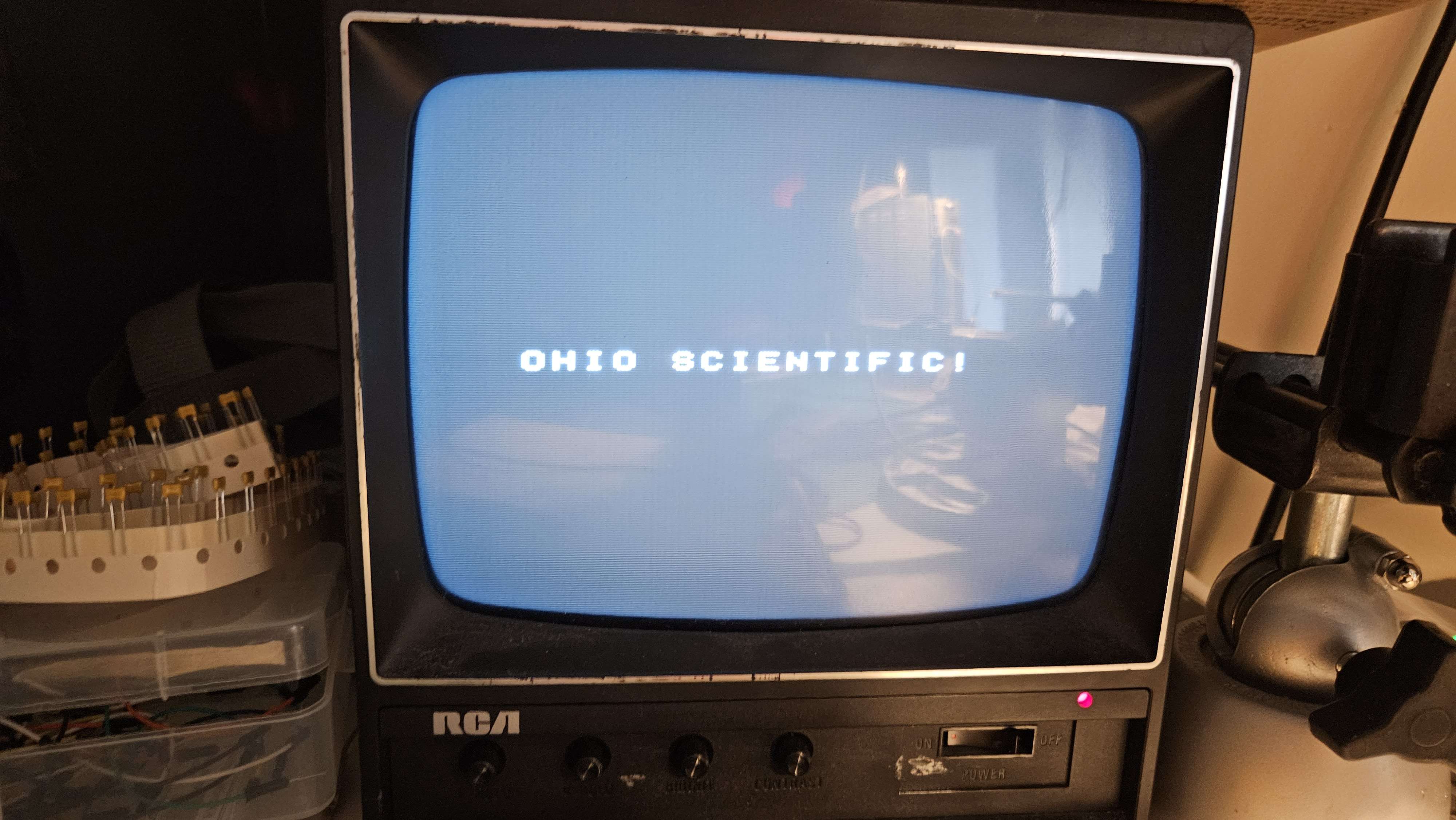
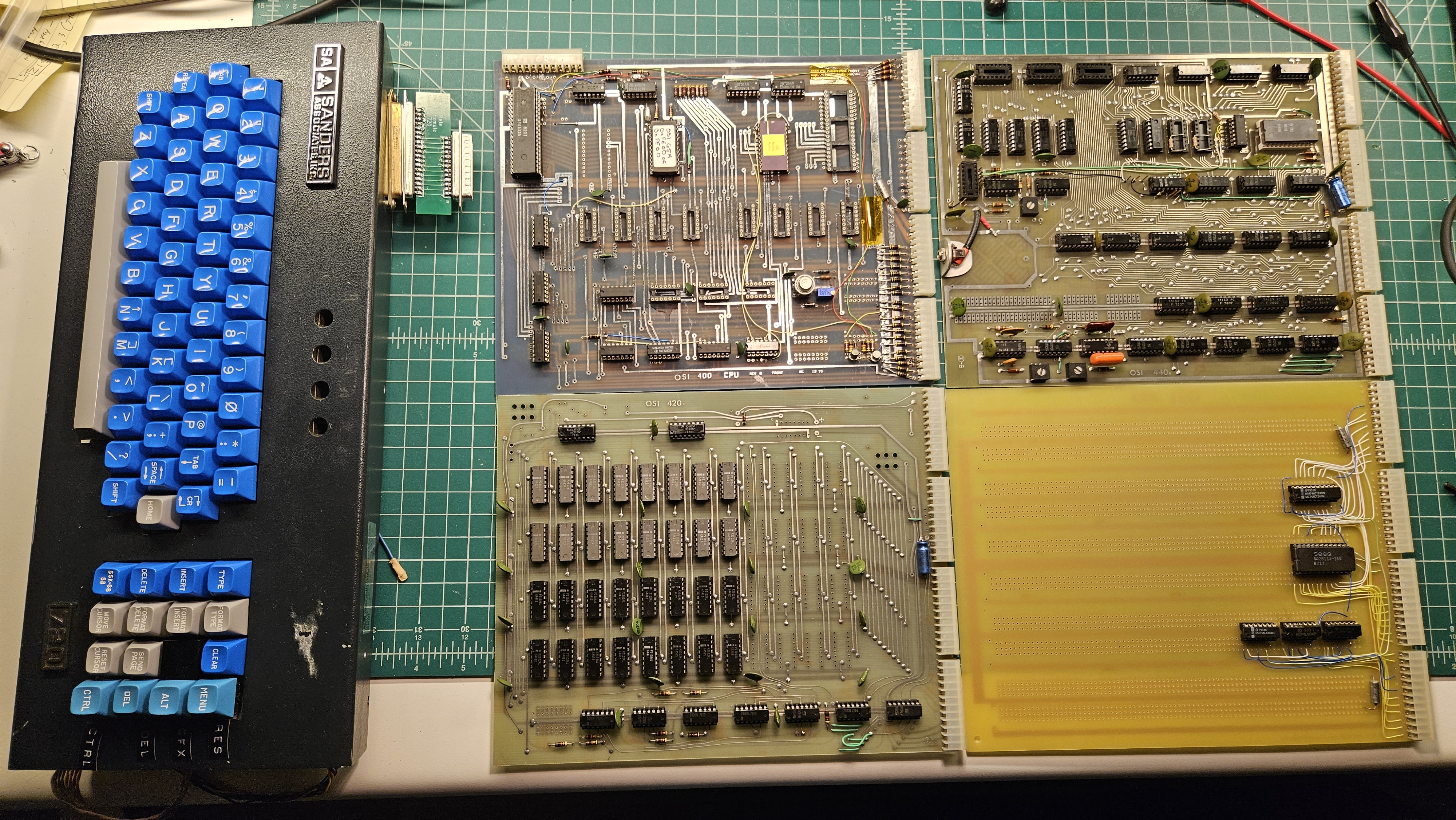
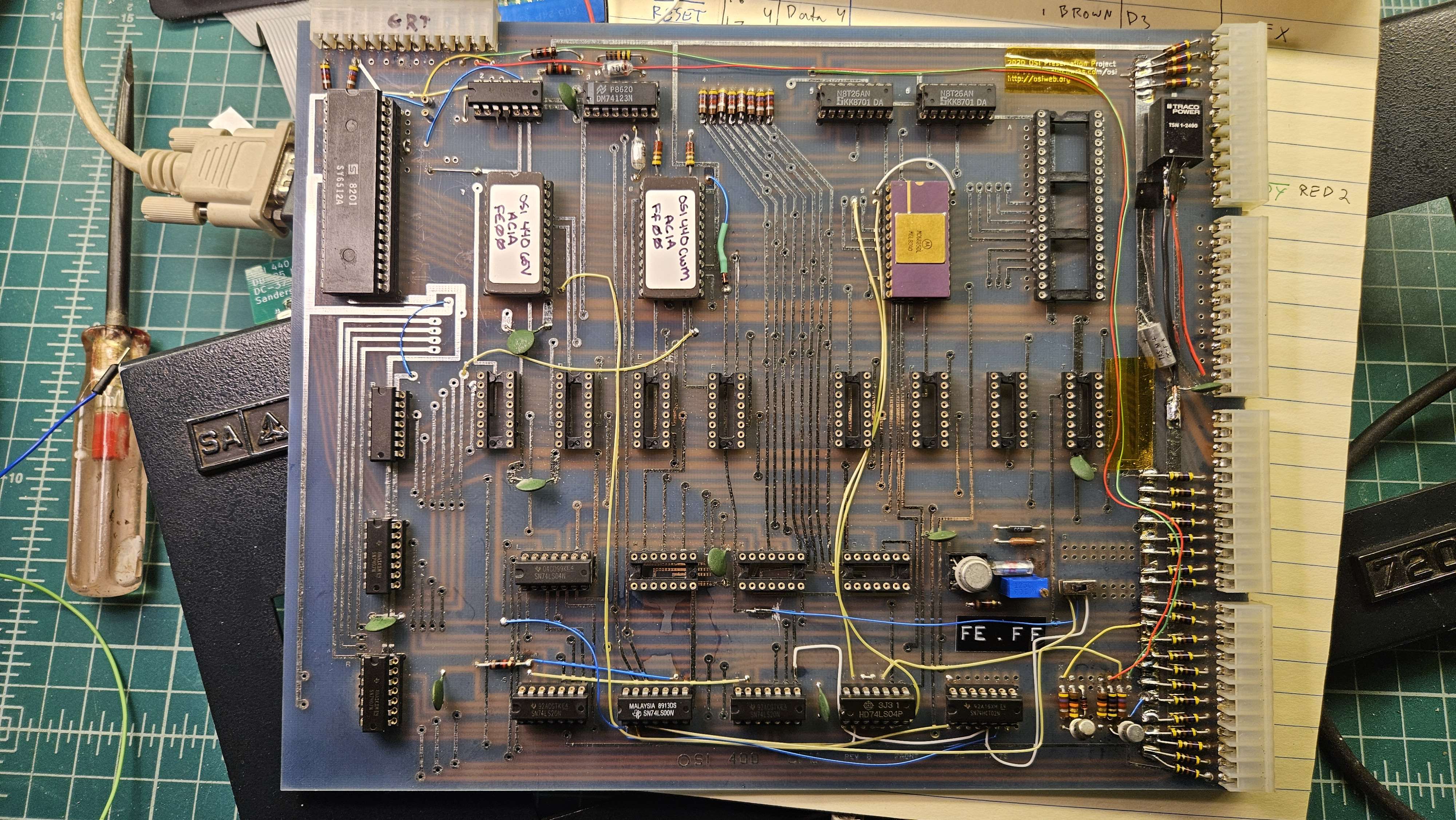
Built my 400 replica

User avatar
CommodoreZ
Posts: 50
Joined: Wed Oct 17, 2018 11:16 am
Contact:

Re: Built my 400 replica

Post by CommodoreZ »

I swear, I'm not slacking over here! :lol:

I added a section on my website with some photos of all the 400 build progress of note: https://www.commodorez.com/osi.html

After returning from a trip, I had my new Sanders 720 keyboard interposer PCBs waiting for me. This board's job is to allow me to toggle the 7th data bit as a CTRL key would, as well as add in a proper Delete key (the 720's native Delete sends the wrong ASCII code). I've also given it places for a key to toggle Graphics mode on the 440 using a 7474, and a Reset switch. Initial tests show that I've probably wired up something wrong on both fronts, but that's not surprising considering how many adapters and whatnot are in the mix. I've only spotted one or two design flaws so far. I've also wired one up to a test harness on the bench, and the ASCII responses seem to be okay, but I have yet to do any testing with it plugged into the 440 beyond a power-on test.
Image

In the meantime, I got frustrated with trying to use what I believe is OS65A (I may be wrong here). I want something I'm more comfortable with to verify the operation of things on the 440, so I elected to assemble the eWoz monitor to a gap in my memory map, $E000, and use a 2816A EEPROM to get it there. Here's the current memory map:

Code: Select all

FE00-FFFF ROM (512B)

FC00-FCFF ACIA (256B)

E400-E7FF Free ROM space
E000-E3FF eWOZ

DC00-DFFF Keyboard (1K, read only)
D400-DBFF Graphics RAM Bank 1 & 2 (2K, 8 bits wide)
D000-D3FF Character RAM (1K, 6 bits wide)

0000-0FFF RAM (4KB)
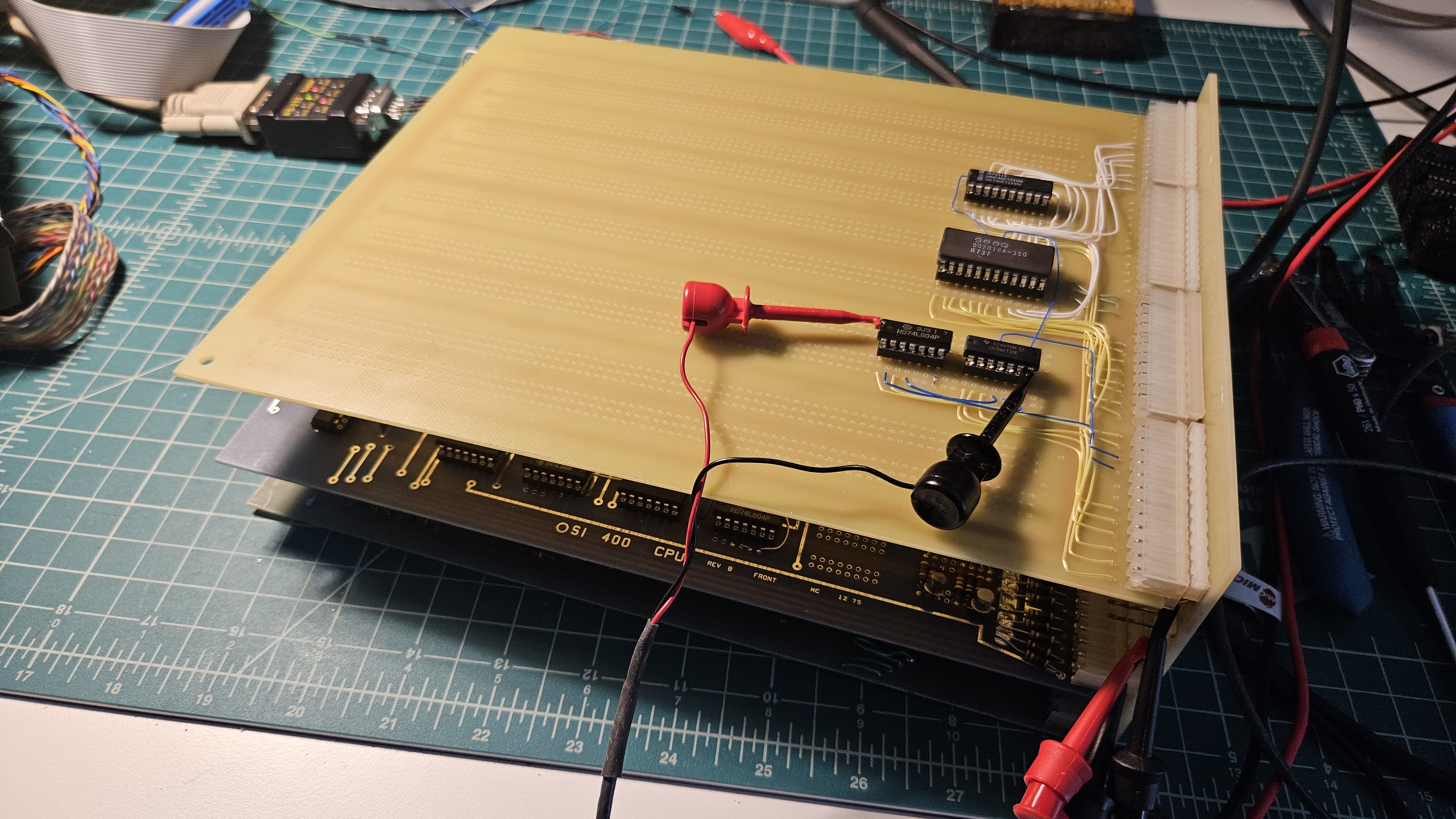
Gotta put that ROM somewhere, and bodging it into the 1702A sockets on the 400 seemed a bit ridiculous, so might as well put that 495 replica to work. Here's the board as a work-in-progress:
Image

So, a few things to note. My decoupling capacitors are on the underside of the board, but I will probably add more to the top side power rails.

I'm using a 74240 instead of 8T26A's on my 495 protoboard to do data bus buffering and inverting. I've seen glitch have success with these buffers on his massive RAM ROM combo board, and liked the convenience factor.

This photo was taken before I installed a Data Direction diode to talk to the 8T26A's. Initially, I did not understand how that data bus buffer operated, but glitch pointed me in the right direction. It kind of blew my mind to think that each board's diode effectively makes one giant OR gate, each capable of signalling the buffers on the CPU board to allow data to be read. I was able to get data other than $FF from a random MCM2716 using this configuration, but thus far I haven't had any luck with the 2816A that I'd prefer to use for convenience sake. I'm still unable to program 2716's with my current equipment, but I worry that these 2816's are too slow either due to my configuration or the 1MHz bus speed.

Right now, I'm reassessing how I'm doing address decoding as it pertains to /OE and /CE qualification, my 74240 buffer, and triggering the DD signal. I'm thinking that I can get the ROM selected first, ignoring the Phi2 or R/W signals initially while the address is being setup, and then open the proverbial flood gates during when Phi2 and R/W are asserted.

I feel like I'm learning alot here!
Last edited by CommodoreZ on Wed Aug 02, 2023 1:00 am, edited 1 time in total.
Superboard Replica (400, 420C, 440) | C4P (502, 540) | Mini OSI-300 | https://www.commodorez.com 🌡
User avatar
CommodoreZ
Posts: 50
Joined: Wed Oct 17, 2018 11:16 am
Contact:

Re: Built my 400 replica

Post by CommodoreZ »

I reconfigured my EEPROM address decoding and buffer qualification circuitry, and I was still getting garbage. I also was reminded about how if I solder just before I go to sleep, I need to check my work when I'm more alert. I double checked my work and found a chip control line attached to 5V that needed to be connected to ground. Once that was sorted, I somehow got from OS65A into eWOZ by accident, and discovered that it didn't want to accept A thru F when inputting hex values. Nor did it print hex values properly. Looking at the characters that it did print, it was as if everything had an offset of $1A. TangentDelta noticed the pattern and pointed out that apparently cl65 had inadvertently ignored my "target" argument when assembling, and instead had targeted the C64, and thus PETSCII codes, not ASCII.

After that problem was sorted, I grappled with my limited understanding of OS65A's syntax. Once again, TangentDelta explained what I was doing wrong. I need to use a command like L012EE000RG to start code at a location. L for load, 012E for the program counter's location in RAM, E000 for the address I wish to jump to, R for reset, and G for "go!". Now that I can get into eWOZ reliably, I feel more comfortable with the interface.

What I still don't understand is why OS65A has been ignoring keystrokes when it is running a Print command (PFF00 for example). The manual indicates that it should see a keypress from me an halt printing, but it does not respond to this behavior. Looking at the disassembly of OS65A, I don't see anything that leads me to believe it needs any interrupt signals connected from the 6850 for that to work, so I'm not sure what's going on there.

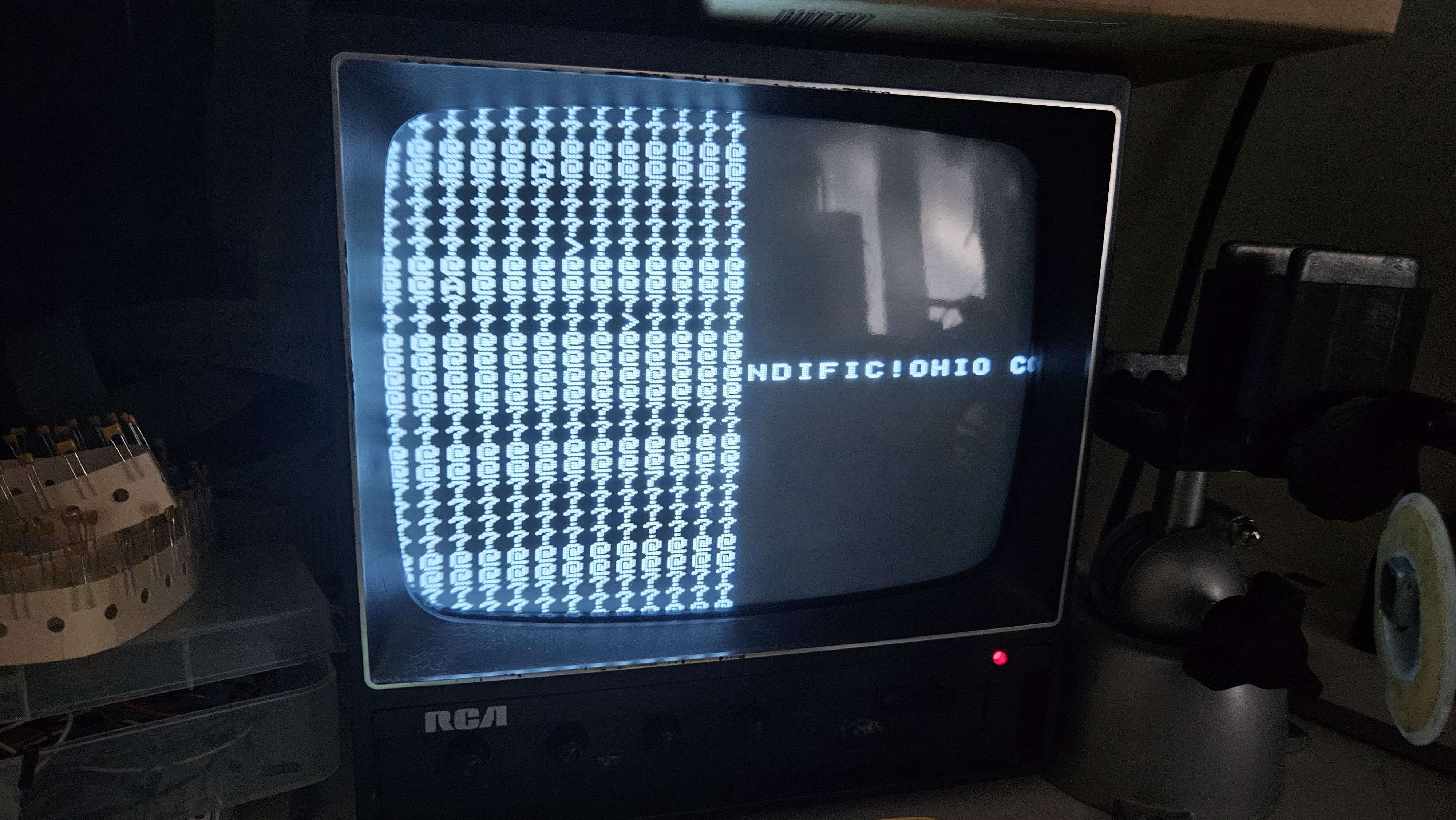
I tried Mark's test program (now that I understand the monitor's commands a bit better), and was getting this on screen:
Image
I tried a number of debugging ideas, thinking that I had failing RAM, something wrong with a data bus buffer, etc. The offset on screen also seemed... peculiar, and the addressing didn't make sense with the type of failure on display. I switched the position of the 440 and the 495 carrying my ROM on the backplane in order to reach various test points, and to my surprise it worked again, but the ROM was no longer accessible.
Image

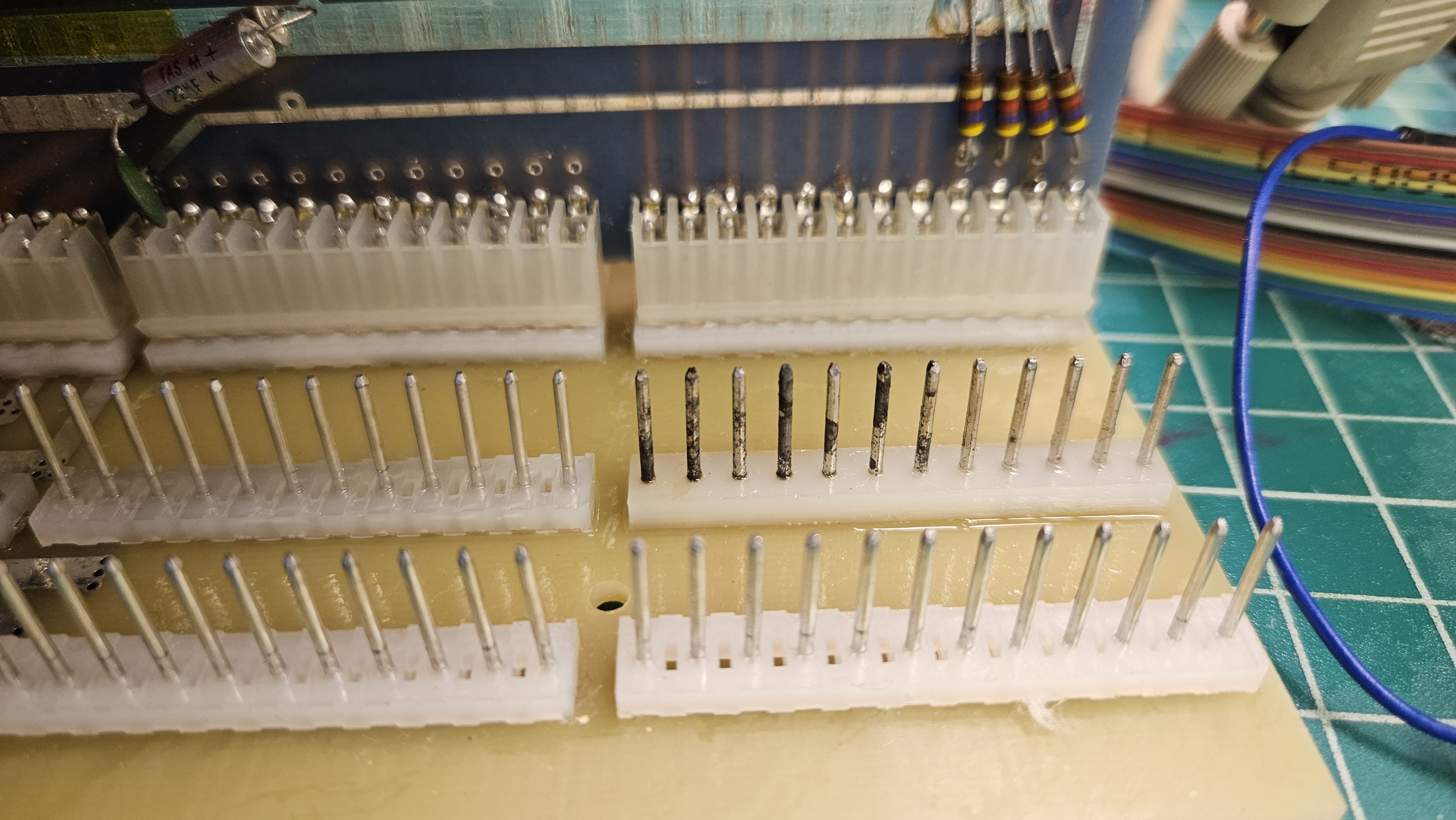
When I was constructing my board, I ran out of new male molex bus connectors, so I had to dip into my supply of used ones. Seems that my 3rd bus slot has more corrosion on it than I realized.
Image
I need to tackle this corrosion, and it's going to take more than deoxit. I've also ordered more connectors for the future, in case I can't clean these sufficiently.

After I take care of that, it's onto debugging the keyboard interface, and figuring out why my RESET, graphics toggle, and of course keyboard data aren't coming through properly. I'm encountering problems in general with this project, but I'm also making progress and learning. I'm not sure how long it will be until I can try burning OS65V for 440-equipped systems to appropriate EPROMs, but I' look forward to trying that too.
Superboard Replica (400, 420C, 440) | C4P (502, 540) | Mini OSI-300 | https://www.commodorez.com 🌡
Mark
Posts: 297
Joined: Tue Sep 16, 2008 6:04 am
Location: Madison, WI
Contact:

Re: Built my 400 replica

Post by Mark »

Hey great progress!

So I'm trying to understand your configuration a bit more.
You should be able to interrupt a Pxxxx dump in the 65A monitor with a character from the serial port. No IRQ is required (or supported).

So at this point, are you are interacting with the 65A monitor using your serial terminal but you have the Sanders keyboard on the OSI440?

I have put together a stand-alone OSI65V monitor for 400/440 system using an ASCII keyboard here. It is a single ROM page that maps to $FF00. It's easier to use and also less useful than 65A (no dump method).

If you have a way to add a BASIC ROM at $A000, you can add the pair of ROMs at $FE00 & $FF00 to have a complete BASIC in ROM system with ASCII keyboard. See OSI440-65V-ACIA.zip. It differs from the other version in that it uses the OSI400 ACIA for serial I/O instead of S1993 UART.

All the files are on my ROMS page.
Cheers!
User avatar
CommodoreZ
Posts: 50
Joined: Wed Oct 17, 2018 11:16 am
Contact:

Re: Built my 400 replica

Post by CommodoreZ »

Image
Mark wrote: ↑Tue Aug 01, 2023 8:38 pm You should be able to interrupt a Pxxxx dump in the 65A monitor with a character from the serial port. No IRQ is required (or supported).
That's what I thought too. I'm not sure why the keypresses are being ignored.

Mark wrote: ↑Tue Aug 01, 2023 8:38 pm So at this point, are you are interacting with the 65A monitor using your serial terminal but you have the Sanders keyboard on the OSI440?
Correct.
The plan is to get the Sanders keyboard working as intended, then break away from 65A and switch to 65V, then see about implementing the routines to use eWOZ with the 440 + Sanders. The point of getting eWOZ installed for serial use first was to have something easier to use to help debug the 720 interface.
Mark wrote: ↑Tue Aug 01, 2023 8:38 pm I have put together a stand-alone OSI65V monitor for 400/440 system using an ASCII keyboard here. It is a single ROM page that maps to $FF00. It's easier to use and also less useful than 65A (no dump method).
Let me make sure I've got this right. There are 3 versions of 440-specific 65V available:
  1. Minimal stand-alone version without a dump method (OSI400-65V-FF00.zip)
  2. The version that works with BASIC (OSI440-65V-ACIA.zip)
  3. The original version that wants a 430 with the S1993 UART (OSI440-65V-440-430.zip)
The only 440-specific 65V version I saw on your ROM page was #3. Any idea why they were trying to use the S1993 UART instead of the 6850? I can't say I've ever looked all that closely at the 430 board before.

It sounds like the second version on that list is what I want so I can use it with BASIC later on. I cannot burn 1702A's at home, so I'm outsourcing that task, and I want to make sure I order the right thing.
Mark wrote: ↑Tue Aug 01, 2023 8:38 pm If you have a way to add a BASIC ROM at $A000, you can add the pair of ROMs at $FE00 & $FF00 to have a complete BASIC in ROM system with ASCII keyboard.
I very much would like to try that too. BASIC is one of my favorite languages on old machines. I thought BASIC wasn't common until the advent of the C1P or systems with more than 4K of RAM, so I wasn't sure if that would be necessarily appropriate to have in ROM for this era of machine. Would any OSI users back in the day have loaded BASIC off of paper tape or cassette tape, rather than have it in ROM?

I tried cleaning the corrosion off of the pins on the bus connectors, no luck there. Flux helped a few of the pins, but the worst of them were unaffected. Abrasive cleaning was doing more harm than good, so I realized I should cut my losses and just swap the old ones for new ones. A fresh batch of those Molex connectors have already been shipped from Mouser.
Superboard Replica (400, 420C, 440) | C4P (502, 540) | Mini OSI-300 | https://www.commodorez.com 🌡
bxdanny
Posts: 335
Joined: Thu Apr 16, 2015 2:27 pm
Location: Bronx, NY USA

Re: Built my 400 replica

Post by bxdanny »

All three versions are now up on Mark's page. Maybe 1 and 2 were just recently added, I'm not sure. The file name for #3 does not include the first "440-".

#2 and #3 were both really sold by OSI, intended for 500 and 400 boards, respectively. #1 was apparently adapted by Mark to make internal JMPs and JSRs refer to $FFxx locations instead of $FExx locations, I guess to allow its use as the only (P)ROM on a board configured for multiple ones. OSI's intent was that the unmodified ($FExx) version could be used stand-alone by not including A8 in the address decoding, making it appear on both $FE and $FF pages.

It should be possible to get the ACIA 65V version working with output to the 440 but input from the serial terminal (PC) on the ACIA by changing one byte, namely the one at $FE16 (or $FF16), from $85 to $86 (STA zero-page to STX zero-page). This will make it come up with the "load from tape" flag set.

When you do get your keyboard working, the version #2 65V could also be used without BASIC by having the 65F or 65F3 (D/M? or H/D/M?) ROM in the $FFxx slot.
No current OSI hardware
Former programmer for Dwo Quong Fok Lok Sow and Orion Software Associates
Former owner of C1P MF (original version) and C2-8P DF (502-based)
User avatar
CommodoreZ
Posts: 50
Joined: Wed Oct 17, 2018 11:16 am
Contact:

Re: Built my 400 replica

Post by CommodoreZ »

It's been awhile since I touched this project, let alone made any progress, but I do finally have an update!

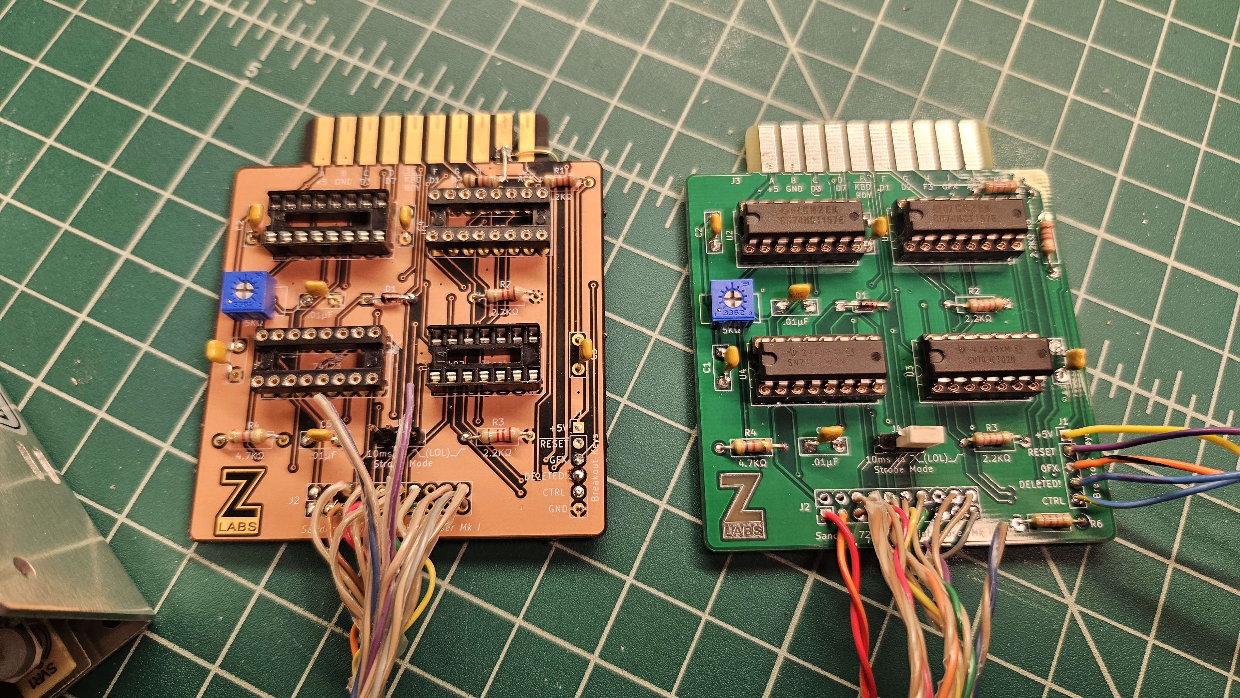
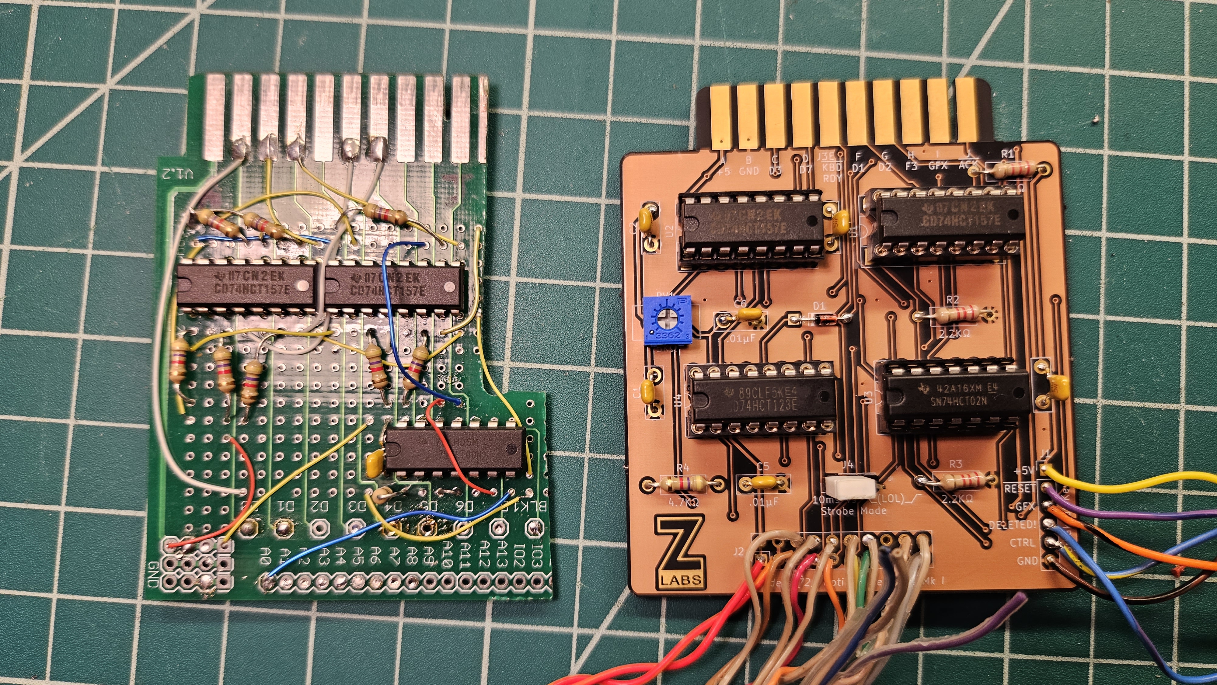
Back in August I discovered there were enough problems with my existing keyboard interposer PCB to warrant a fresh revision of the board. The result is this green PCB you see on the right, which has fixed a few things. It tested fine on the bench setup, which is good.
Image

I remember trying it with the 440 and discovering that the keyboard still didn't work right. In particular, I wasn't seeing the keyboard strobe firing any more, which lead me down the rabbit hole of debugging the keyboard itself. The project stalled just prior to VCF Midwest in early September. At the time, the suspected point of failure was the analog OR gate circuit using an op-amp to detect key presses. The tolerance of the resistors in circuit was tested fine, then I just didn't touch it out of frustration.

Until this week! I soldered those resistors back in, and tried my hand at replacing the drive transistor in that circuit that feeds into the op-amp. While it tested okay compared to its replacements, I still wanted to replace it. With the new one in, I verified the keyboard strobe was good on the test harness, and then tried it again with the 440. Once again, no keyboard strobe. So I checked my work, and discovered that the issue was the +/-15V differential voltage being provided for the op-amp. The +15V rail was too high by about 2.3V, and the reference circuit considers that out of spec for the LM201 to trigger based on the output of the keyboard matrix, so it wouldn't trigger the strobe. I've installed a diode to add enough voltage drop to fix the issue, since adjusting the PSU output affects all the rails equally, not just the +15V rail.

With that solved, I'm getting keyboard scan codes again using a test program written by TangentDelta to show me the ASCII values over serial. Now the issue is why 65V isn't booting properly. I've modified the 400 board to accept two 1702A EPROMs per the manual, and I've included a switch to let me select either a single 1702 with 65A or two with 65V. However, I need to verify my circuitry, as I did this rework back in August. Below the switch label of FE . FF is the logic handling chip selection in dual-1702 mode.

Image
Superboard Replica (400, 420C, 440) | C4P (502, 540) | Mini OSI-300 | https://www.commodorez.com 🌡
User avatar
CommodoreZ
Posts: 50
Joined: Wed Oct 17, 2018 11:16 am
Contact:

Re: Built my 400 replica

Post by CommodoreZ »

So, over the past few days I've made some interesting progress, and learned about a few quirks.

I did a fresh install of cc65 and re-assembled 65V into the E000 bank of my EEPROM, as I lack the ability to burn 1702A's still. Jumping to it from 65A is no trouble, and I get the text on screen. Considering I had alot of trouble with ca65/ld65, this is a welcomed change of pace. I have Ben Eater to thank for that one.

However, when I start to type, it's as if I've typed the same character repeatedly: https://www.youtube.com/watch?v=uwkTOCk-ZYE
Initially I thought this was something wrong with the code, so I looked over the keyboard input handler instructions, and it very clearly waits until the key strobe is released before considering that a full key press. I checked the strobe on my analog scope and it looked solid, not bouncy at all. Then I checked it out on the DSO...
strobe flicker.jpg
strobe flicker.jpg (1.04 MiB) Viewed 1987 times
For some reason, the pulses on the Sanders 720 keyboard strobe generator one-shot have these glitches in retrigger mode, which the 440 sees as distinct key presses. Initially, I thought it was noise in the keyboard cable from some other signal, but it was too uniform, too strong. For fun, I threw a ceramic capacitor to ground on the strobe line to dampen these out, and allowed a single character per press, rather than rapid fire. But this is a hack not a fix.

I've isolated the problem to the sections highlighted in yellow.
image.png
image.png (455.16 KiB) Viewed 1987 times
Chips Z10, Z5, and Z4 create a feedback loop, but Z10 is suspected of being the origination point. At this time, the plan is to remove Z10 (an old Fairchild 9601) and test it in retrigger mode without letting it loop back on itself.

Still, nice to see for a moment that OS65V worked as intended. It does feel rather clunky, I can see why people would have preferred more advanced approaches. Progress!

Question: I've found mention of OSI BASIC being available on paper tape for original 400-based Challenger machines with serial and 12K or more of RAM. It was in a very old OSI BASIC manual. Do we know if this version was preserved?
Superboard Replica (400, 420C, 440) | C4P (502, 540) | Mini OSI-300 | https://www.commodorez.com 🌡
bxdanny
Posts: 335
Joined: Thu Apr 16, 2015 2:27 pm
Location: Bronx, NY USA

Re: Built my 400 replica

Post by bxdanny »

I seriously doubt that any paper tape copies of OSI BASIC have survived. But the BASIC itself would almost certainly have been the same version that was used with OS-65D 2.x (and maybe 1.x), which was essentially identical to the ROM version, but assembled at $0200 rather than $A000. I believe it even signed on with the same VERSION 1.0 REV 3.2 message. I did see it once, briefly, but didn't get a chance to test if it had the same fatal "string bug" relating to garbage collection. An odd thing about that 65D 2.x is that it depended on the hard-coded $2200 execution start address in the boot ROM. Track 0 actually loaded to $2180, but that first 128 bytes contained some kind of data, and had to be skipped over.

BTW, that is one impressive-looking scope in your picture.
No current OSI hardware
Former programmer for Dwo Quong Fok Lok Sow and Orion Software Associates
Former owner of C1P MF (original version) and C2-8P DF (502-based)
User avatar
CommodoreZ
Posts: 50
Joined: Wed Oct 17, 2018 11:16 am
Contact:

Re: Built my 400 replica

Post by CommodoreZ »

bxdanny wrote: ↑Thu Jan 25, 2024 6:28 pm I seriously doubt that any paper tape copies of OSI BASIC have survived. But the BASIC itself would almost certainly have been the same version that was used with OS-65D 2.x (and maybe 1.x), which was essentially identical to the ROM version, but assembled at $0200 rather than $A000.
Bummer. Sounds like it might be worth trying to reassemble a version at that address. I've also heard there are tiny BASICs out there for more RAM-constricted machines. I'm still deciding how I want to approach that part. For now, I'm just happy that 65A, 65V, and eWOZMON have all worked on my 400.
20240125_074604.jpg
20240125_074604.jpg (2.67 MiB) Viewed 1867 times
bxdanny wrote: ↑Thu Jan 25, 2024 6:28 pm BTW, that is one impressive-looking scope in your picture.
I'll be honest, I find the Rigol's interface very slow and unintuitive. I tend to default to my Tek 2245B, but that's how I missed the problem in the first place.

I desoldered the 9601 and tested it out of circuit. That thing was a fight to remove. Replacement has been ordered, should be here within a few days.
20240125_100038.jpg
20240125_100038.jpg (2.34 MiB) Viewed 1867 times
20240125_100017.jpg
20240125_100017.jpg (2.96 MiB) Viewed 1867 times
Superboard Replica (400, 420C, 440) | C4P (502, 540) | Mini OSI-300 | https://www.commodorez.com 🌡
bxdanny
Posts: 335
Joined: Thu Apr 16, 2015 2:27 pm
Location: Bronx, NY USA

Re: Built my 400 replica

Post by bxdanny »

CommodoreZ,

I have a general question about ASCII keyboards like the one you are using. When the strobe pulse is over with, do the other seven bits retain the value of the last key pressed? Or do they all go high, or all low? To your knowledge, was there any consistency between brands and models about this, or did each manufacturer just do whatever was convenient?
No current OSI hardware
Former programmer for Dwo Quong Fok Lok Sow and Orion Software Associates
Former owner of C1P MF (original version) and C2-8P DF (502-based)
Post Reply