Hello,
I'm cobbling together a new C4PMF (sold my old one years back) using a 505, 527 and 540 board and a C4P case. The case has a single (original) PSU with brown and red wires feeding the 4-slot 582 board. Based on C4PMF's I've seen in the past, it looks as if I need to supplement the original PSU to sufficiently power the 527 board. Is there a resource anywhere that provides specs for the additional PSU, how to wire the original and additional PSU's together (if that's appropriate) and what the configuration should be for connecting wires from the PSU's to the 582?
Thanks
Power supply hookup for C4PMF
-
lowrybt1
- Posts: 212
- Joined: Sun Mar 08, 2015 3:42 pm
- Location: New York State
Power supply hookup for C4PMF
C8PDF w. 48K, 2x 520 24K RAM boards and Glitchworks 64K board
OSI 567 Telephony board
Spare 8" drives
Klyball D-13
OSI 567 Telephony board
Spare 8" drives
Klyball D-13
-
Mark
- Posts: 297
- Joined: Tue Sep 16, 2008 6:04 am
- Location: Madison, WI
- Contact:
Re: Power supply hookup for C4PMF
My C4PMF came with two identical standard 5V OSI power supplies. One powered the lower two slots, the other powered the higher two. There was no direct 5V electrical connection between the two. They never seemed to be quite the same voltage, although they were generally within 1/4 volt of each other. Eventually I replaced them with a modern switcher when one failed. I think this helped with the overall stability of the system.
-
CommodoreZ

- Posts: 50
- Joined: Wed Oct 17, 2018 11:16 am
- Contact:
Re: Power supply hookup for C4PMF
I've done the same for the C4P (the ROM BASIC version). I threw a Lambda at the problem with an abundance of amperage, and had 12V available to feed a case fan, but I can't imagine you would need more than 4 or 5A even with all that SRAM. The hardest part was making a mounting bracket to hold the PSU. I think it was glitch who told me that OSI used their 12V supply but tuned it for 5V, resulting in a lot of extra heat generated, which rendered the case of my C4P untouchable after less than an hour of operation.
Superboard Replica (400, 420C, 440) | C4P (502, 540) | Mini OSI-300 | https://www.commodorez.com 

-
Thomas
- Posts: 29
- Joined: Tue May 30, 2023 8:53 am
Re: Power supply hookup for C4PMF
My recommendation would be the same, to make use of a more modern PSU replacement. On my C1P with 610 RAM board, the 5V line has to provide 5.4 amps. Using 2 of the original PSUs creates a lot of heat and stress to the regulators. And that’s is still without the power needed for two external drives.
-
Scott Larson
- Posts: 33
- Joined: Fri Nov 14, 2008 8:32 pm
Re: Power supply hookup for C4PMF
That was one of the first things I did with my C1P when I went to college back in 1985. There was no reason to keep using the hot and noisy linear power supply it came with when there were lots of silent and inexpensive switching power supplies available. They're even smaller and cheaper now.
-
Mark
- Posts: 297
- Joined: Tue Sep 16, 2008 6:04 am
- Location: Madison, WI
- Contact:
Re: Power supply hookup for C4PMF
I took a look at the original power supplies from my C4PMF.
They are both 5V 3A supplies apparently.
I don't remember the C4P getting unusually hot, but the late 70's 110V muffin fan was certainly loud!
5V @ 3A x2
The original supplies are easy to fix up, but why rely on LM723 based regulators?
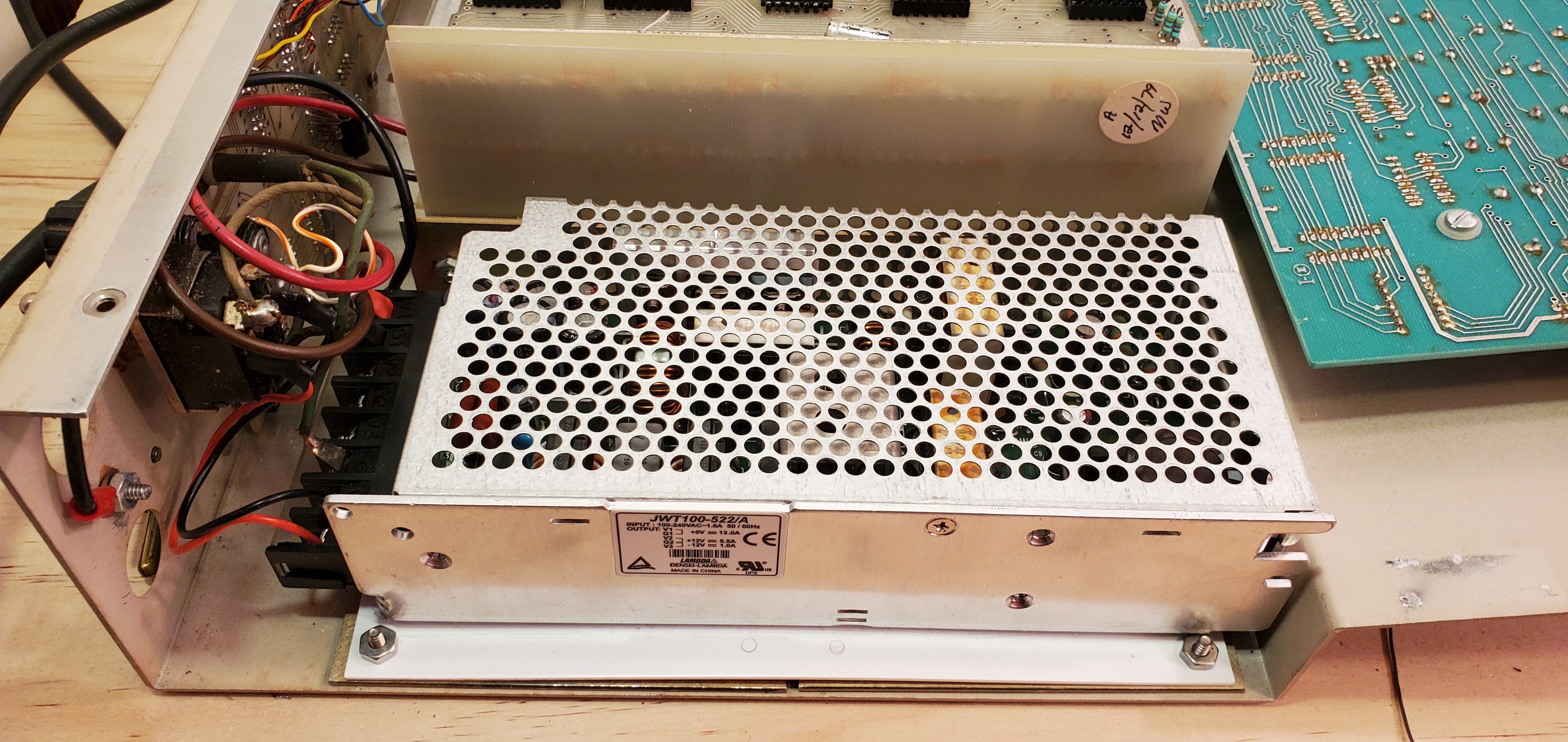
The new switcher has enough juice to power the external floppy drive. But the 12v regulation is based on 5v load. Boooo. Fortunately FlashFloppy only uses +5V
The original 527 board has been replaced with a custom CMOS 6264 based board which uses hardly any power.
They are both 5V 3A supplies apparently.
I don't remember the C4P getting unusually hot, but the late 70's 110V muffin fan was certainly loud!
- Pair o'supplies
- DSCN1124s.jpg (284.66 KiB) Viewed 12629 times
- Ratings
- DSCN1138s.jpg (138.51 KiB) Viewed 12629 times
- Front
- front#1.jpg (1 MiB) Viewed 12629 times
- Replacement
- DSCN1134s.jpg (369.83 KiB) Viewed 12629 times
-
dave
- Site Admin
- Posts: 717
- Joined: Tue Sep 09, 2008 5:24 am
Re: Power supply hookup for C4PMF
My C2-4P system also had two power supplies, one for the backplane, and one powering the 527 board via the separate power connector on the side of the 527 board. The +5V and GND lines of the 527 were disconnected from the bus connectors.